Power Wiring:
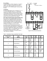
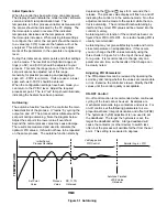
Connect terminals as shown in Figure 4.3. The power
switch S1 and Fuse F1 are included for illustrative
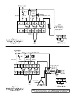
purpose only. Refer to Figures 4.4, 4.5, 4.6, 4.7, 4.8,
4.9, and 4.10 on the following pages for sample wiring
diagrams.
Input Wiring:
Connect the appropriate sensor to terminals 12, 13, 14,
15 or 16 as illustrated in Figure 4.3. Verify that the
instrument is selected for the correct sensor and the
correct polarity is observed at both the sensor-end and
instrument-end of the cable. Do not run sensor cables
in the same conduit or wiring trough as the power lines,
because the low level signal is noise sensitive.
When wiring the thermocouple, check the thermocouple
and extension wire (compensating cable) to make sure
they conform to the appropriate thermocouple type
specified by the instrument. Extension wires must be
the same alloy and polarity as the thermocouple. The
total lead resistance should not exceed 100 ohms for
accurate measurements. One hundred ohms of lead
resistance will introduce a 1°F (0.5°C ) error.
For wiring 3 wire RTD (Resistance Temperature
Detector) all leads connecting the RTD to the controller
must be the same gauge and material. If the RTD is a
3 wire device, install the two common wires of the RTD
to terminals 13 and 14. If a 2 wire RTD is to be used,
install a jumper between terminals 13 and 14.
See page 22 for instructions to re-range the input to
volts, milli-volts or milli-amps.
1
2
3
4
5
6
7
8
9
10
11
12
13
14
15
16
+
+
+
+
–
–
–
0-20mA
4-20mA
V
0-10V
RTD
A
B
B
T/C
PTA
TC–
MV–
TC+
COM+
mA–
V–
MV
90-264
VAC
50/60Hz
ALARM 2
OUTPUT 2
ALARM 1
OUTPUT 1
Power
Input:
S1
F1
V
Pulsed
Voltage
Current
+
+
–
–
V
Pulsed
Voltage
Current
N
L
Relay
(or)
Low Voltage
on Specific
Models
–
Polarity makes no difference
(or Triac)
Optional
Retransmission
Output.
Refer to page 21 for
Instructions.
Figure 4.3 Rear Terminal Connections
Thermocouple
Cable
American
British
German
French
Type
Material
ANSI
BS
DIN
NFE
1843
43710
18001
J
Iron/Constantan
+ white
- red
* black
+ yellow
- blue
* black
+ red
- blue
* blue
+ yellow
- black
* black
K
Chromel/Alumel
+ yellow
- red
* yellow
+ brown
- black
* red
+ red
- green
* green
+ yellow
- purple
* yellow
T
Copper/
Constantan
+ white
- blue
* blue
+ blue
- red
* blue
+ red
- brown
* brown
+ yellow
- black
* black
R
S
Platinum/Rhodium
+ white
- blue
* green
+ black
- red
* green
+ red
- white
* white
+ yellow
- green
* green
B
Platinum/Rhodium
+ grey
- red
* grey
+ red
- grey
* grey
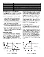
Table 4.1 International Thermocouple Cable Color Codes
* Color of overall sheath
Chromel® and Alumel® are registered trademarks of Hoskins Mfg. Co.

