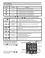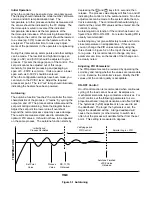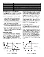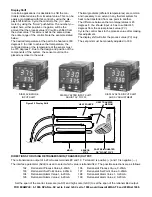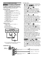
Return control to:
1) Press latches on each side to remove rear terminal
block.
2) To remove PCB assembly from housing, insert two
small screw drivers between the PCB and housing top
and bottom. This will expand the housing and release
the locking tabs. Then pull the PCB assembly out of
the housing.
Section 7: TROUBLESHOOTING
THIS PROCEDURE REQUIRES ACCESS TO THE CIRCUITRY OF A LIVE POWER UNIT.
DANGEROUS ACCIDENTAL CONTACT WITH LINE VOLTAGE IS POSSIBLE. ONLY QUALIFIED
PERSONNEL ARE TO PERFORM THESE PROCEDURES. POTENTIALLY LETHAL VOLTAGES ARE PRESENT.
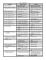
Experience has proven that many control problems are not caused by a defective instrument. See chart below and
Table 7.1 on the next page for some of the other common causes of failures:
WARNING!
Incorrect parameters entered in menu.
Excessive electrical interference.
Line wires are improperly connected.
No voltage between line terminals.
Incorrect voltage between line terminals.
Connections to terminals are open, missing or loose.
Thermocouple (or RTD) is open at tip.
Thermocouple (or RTD) lead is broken.
Shorted thermocouple (or RTD) leads.
Short across terminals.
Open or shorted heater circuit.
Open coil in external contactor.
Burned out line fuses.
Burned out relay inside control.
Defective solid-state relays.
Defective line switches.
Burned out contactor.
Defective circuit breakers.
If the points listed on the chart have been checked and the controller does not function, it is suggested that the
instrument be returned for inspection.
Do not attempt to make repairs. Also, it is advisable to use adequate packing materials to prevent
damage in shipment.

