background image

The proportional band (Pb) is a temperature band
expressed in degrees.  When the controller is within this
band, the time proprtioning functions are active.

Integral action (automatic reset) corrects for offset (load
error) for load variations. Reset wind-up inhibition prevents
integral action from occurring outside of the proportional
band. Software antisaturation minimizes process oscilla-
tions when the load changes.

Derivative action is adjusted to match the response time of
the process and to compensate the integral action.
Correct adjustment provides power output compensation
for process load variations. It also minimizes overshoot
and oscillations at start up or in large process upsets.
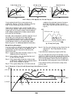
Refer to Figure 5.1 for additional adjustment instructions.

Manual Tuning Procedures:

For some systems it is difficult to execute automatic tuning
or the automatic tuning results are not satisfactory. The
following steps can then be used for initial tuning of a
three-mode control:

Step 1: Adjust the integral and derivative values to 0. This

inhibits the rate and reset action.

Step 2: Set an arbitrary value of proportional band and

monitor the control results.

Step 3: If the original setting introduces a large process

oscillation then gradually increase the proportional
band until the oscillation disappears.

Step 4: If the original setting does not introduce process

oscillations then gradually decrease the propor-
tional band until steady cycling is observed.
Record this important proportional band percent-
age (Pc).

Step 5: Time the period of steady cycling. Record this crit-

ical period Tc. The PID parameters are deter-
mined as:

This method was developed by Ziegler and Nichols.

If you are unfamiliar with tuning PID Controllers, we sug-
gest that you obtain and become familiar with the following
reference material: Tuning of Indusrial Control Systems
by A.R. Corripio ISBN: 1-55617-253-2-Q. Available from:
ISA Publications and Training Aids, phone: 919-549-8411.

This method should be performed with a temperature
chart recorder.

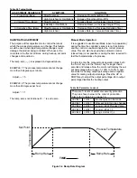
Fig. 5.2 Steady State Cycling

TIME

PV (Process value)

PV

Tc

P Band (Pb) = 1.7 Pc
Integral Time (ti) =  Tc
Derivative Time (td) = 0.125 Tc

PV

UPPER PB

SET POINT

LOWER PB

PI

PID

PD

P

OFFSET

PROPORTIONAL BAND

TIME

Perfect

Proportional Band Too Low

Proportional Band Too High

SP

PV

TIME

PROPORTIONAL ACTION

Derivative Too High

Perfect

Derivative Too Low

TIME

SP

PV

DERIVATIVE ACTION

INTEGRAL ACTION

PV

SP

Integral Too High (Too long for recovery)

Perfect

Integral Too Low

TIME

FIG 5.1 Effects of PID Adjustment on Process Response

Fig. 5.3 Response of a Typical Control System Using Various Modes of Control

Содержание ETR-9090

Страница 1: ...MANUAL NO 14A SOFTWARE VERSION 3 3 AND HIGHER Model ETR 9090 Microprocessor Based SMARTER LOGIC Auto Tune PID Controller INSTRUCTION MANUAL SMARTER SMARTER LOGIC LOGIC LOGIC ...

Страница 2: ...displays show process and set point values at a glance Precise 14 slope sensor linearization self diagnostic capability cold junction compensation and 3 mode PID calculations are automatically executed by the single chip microproces sor The wide selection of parameters values sensor types set points control modes alarm modes degrees C F and security codes are held in a non volatile memory and reta...

Страница 3: ...0 264 VAC 50 60 Hz 20 32VAC DC and 10 16VDC available Input Type J K R T B E S N thermocouple PT100 ohm RTD DIN 43760 BS1904 or JIS and 10 to 60mV given span Power consumption Less than 5VA Accuracy 1 least significant digit ETR 9090 1 2 3 LINE ONE SIGNAL INPUT 1 Thermocouple J K T E B R S N 2 RTD PT100 ohms Alpha 0 00385 DIN43760 3 RTD PT100 ohms Alpha 0 00392 JIS 4 Voltage 10 to 60 mV current or...

Страница 4: ...s Voltage output 0 10V isolated minimum impedance 500K ohms Pulsed voltage 24VDC unisolated max current 20mA Relay 3A 240V Resistive load for heating 2A 240V Resistive load for alarm Control Action Heating relay closed on temperature rise or cooling relay open on temperature rise front panel selectable NON VOLATILE MEMORY Retains process parameters when power is off EXTERNAL LOCKOUT CODE Prevents ...

Страница 5: ...g verify the label for correct model num ber and options Switch off the power when checking Care must be taken to ensure that maximum voltage ratings specified in Section 3 on previous page are not exceeded It is recommended that power to these instruments be protected by fuses and circuit breakers rated at the minimum value possible All units should be installed inside a suitably ground ed metal ...

Страница 6: ... 3 wire RTD Resistance Temperature Detector all leads connecting the RTD to the controller must be the same gauge and material If the RTD is a 3 wire device install the two common wires of the RTD to terminals 4 and 5 If a 2 wire RTD is to be used install a jumper between terminals 4 and 5 Figure 4 3 Rear Terminal Connections 1 2 3 4 5 6 7 8 9 10 F1 S1 Current Voltage Control Pulsed Voltage O P C ...

Страница 7: ... 4 Solid State Relay Heaters Red This diagram can also be used for controls with 4 20mA output Heater Fuse Heater Power Figure 4 4 Example of wiring connections for ETR 9090 122 with Relay Output Figure 4 5 Example of wiring connections for ETR 9090 132 with Pulsed Voltage Output for Solid State Relay B B A 3 4 5 RTD Sensor Connections Note control label for incoming power requirements CAUTION SHO...

Страница 8: ...o o o Three Phase Heater Power 3 Pole Magnetic Contactor NEMA or DP Three Phase Delta Heater Load Alarm 2 Amps Maximum Alarm Relay Heater Fuses Red Figure 4 6 ETR 9090 121 with Relay Output Heaters connected in 3 Phase to Contactor With Alarm option Note control label for incoming power requirements ...

Страница 9: ...evice placing more than one thermocouple in parallel will provide an average temperature reading and produce better results in most air heated processes Proper sensor type is also a very important factor in obtaining precise measurements The sensor must have the correct temperature range to meet the process requirements In special processes the sensor might have to have different requirements such...

Страница 10: ...er Decreases the parameter Set point or other Resets the controller to its normal status Also stops auto tuning output percentage monitoring and manual mode operation Allows more parameters to be inspected or changed 1 Executes auto tuning function 2 Calibrates control when in calibration level Allows the set point display to indicate the control output value in percent Allows the controller to en...

Страница 11: ...eturn key can be pressed at any time This will prompt the display to return to the Process Value Set Value Power Applied 1 Displayed for 4 seconds Software Version 3 3 or higher 2 LED test All LED segments must be lit for 4 seconds 3 Process value and set point indicated WARNING Do not enter Level 4 unless you have proper calibration instruments Refer to Page 19 for further information ...

Страница 12: ... 18 F Low limit minus set point high limit minus set point IF ALAI 2 3 6 or 11 Ramp Rate for the process value Limits an abrupt change of the process temperature Soft start 0 360 F 0 200 C minute If in 0 90 0 0 0 3600 minute If in 10 Offset Value for Manual Reset Only used if integral is 0 0 0 0 to 100 Offset shift for process value 199 count to 199 count 0 0 See page 18 for instructions Proportio...

Страница 13: ...ero The oFST than func tions the same as manual reset to correct the process tem perature to the set point temperature If the process tem perature stabilizes below the set point set a positive amount of oFST If the process temperature stabilizes above the set point set a negative amount of oFST Wait for the system to stabilize and make further adjustments as required The number observed in this pa...

Страница 14: ...ysteresis is set the larger the deadband will be A large deadband will cause the contactor or other device to switch less often but the process will oscillate farther from the set point This setting is measured in degrees Adjusting PID Parameters The PID parameters can be reviewed by operating the scroll key and noting whether the values are reason able or not Examine the controller s result Modif...

Страница 15: ...process oscillation then gradually increase the proportional band until the oscillation disappears Step 4 If the original setting does not introduce process oscillations then gradually decrease the propor tional band until steady cycling is observed Record this important proportional band percent age Pc Step 5 Time the period of steady cycling Record this crit ical period Tc The PID parameters are...

Страница 16: ...uct being controlled When used the ramp rate is in effect at all times during heat up set point changes and cool down The ramp rate is expressed in degrees minute EXAMPLE 1 The process temperature cannot change more than 5 degrees per minute Adjust 5 EXAMPLE 2 The process temperature cannot change more than 60 degrees per hour Adjust 1 The ramp rate is not functional if is set to zero Manual Mode ...

Страница 17: ...t active the first incident Alarm is not active the first incident SV INHIBITED DEVIATION HIGH ALARM Alarm is not active the first incident Alarm is not active the first incident ASP1 INHIBITED DEVIATION LOW ALARM SV Alarm is not active the first incident INHIBIT INBAND ALARM SV DWELL TIME OUT RELAY OFF SOAK CONTROL Once set point is reached timer is activated MINUTES SV DWELL TIME OUT RELAY ON SO...

Страница 18: ...ion may be used to control external devices such as lights bells or locks It could also be used to alert the operator when a guaranteed soak time has been reached To use this function set ALA1 to 13 The alarm relay will now operate as a timer The relay will be open at start up Once the set point temperature has been reached and the time period set in ASP1 has elapsed the alarm relay will close The...

Страница 19: ...he desired temperature at the part to be heated is 330 degrees F In order to achieve that temperature the DISPLAY BEFORE INPUT SHIFT DISPLAY AFTER INPUT SHIFT ADJUST SV TO 330 Figure 5 5 Display Shift controlling value or the temperature at the sensor must be 375 degrees F Due to the design and position of the components of the system the sensor could not be placed any closer to the work Thermal g...

Страница 20: ...after the calibration procedure is com pleted 2 Press the scroll button again for a long scroll and the low calibration parameter will be displayed Adjust the input simulator to the value indicated in the chart to the right This value must also match the value in the controls display Correct if necessary Press the button for exactly 6 seconds to calibrate the low or zero calibration point 3 Press ...

Страница 21: ...ther common causes of failures WARNING Incorrect parameters entered in menu Excessive electrical interference Line wires are improperly connected No voltage between line terminals Incorrect voltage between line terminals Connections to terminals are open missing or loose Thermocouple or RTD is open at tip Thermocouple or RTD lead is broken Shorted thermocouple or RTD leads Short across terminals O...

Страница 22: ...input mode selected Analog portion A D converter defective Reversed input wiring of sensor No heater power output incorrect output device used Output device defective Open fuse outside of the instru ment Output device shorted or power service shorted CPU or EEPROM non volative memory defective Key switch defective Operation of control incorrect Electromagnetic interference EMI or Radio Frequency I...

Отзывы: