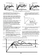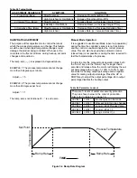
Section 6: CALIBRATION PROCEDURE
Changing these values can make the control useless because it can be put out of calibration. Do not
attempt to re-calibrate this temperature controller unless you have an adequate calibration instrument
available. This must be used to simulate the sensor input.
WARNING!
The controller must operate under power for at least 45
minutes before starting the calibration procedure. This
allows the internal components to reach the proper
operating temperature. Connect the calibrating instru-
ment to the ETR control and power leads.
STEP:
1.) Press and release the scroll key (
) cycling
through the parameters to make certain they are cor-
rect. Note the display flow chart on pages 10 & 11. Long
scrolls (pressing the button for 6 seconds) must be used
where indicated. Check parameters such as ,input
type, degrees C or degrees F and resolution. The span
of the control (
) and (
) must be extended out
to their maximum values. Example: when using a type
“J” thermocouple the low range value
must be –58
degrees F (–50 deg. C) and the high range value
must be 1832 degrees F (1000 deg. C). These values
are listed in the chart on page two for other sensor
types. The span of the control can be narrowed to your
preferred range after the calibration procedure is com-
pleted.
2.) Press the scroll button again for a long scroll and the
low calibration parameter (
) will be displayed.
Adjust the input simulator to the value indicated in the
chart to the right. This value must also match the value
in the controls display. Correct if necessary. Press the
button for exactly 6 seconds to calibrate the low (or
zero) calibration point.
3.) Press the scroll button again and the high calibration
parameter (
) will be displayed. Adjust the input sim-
ulator to the high calibration (span) value as indicated in
the chart. Adjust the controller to the same value. Press
the button for exactly 6 seconds to calibrate the
high (or SPAN) calibration point.
4.) The calibration is now complete. Press the scroll but-
ton again and process value and setpoint value will
appear.
Check intermediate values to test mid-range calibration
accuracy. The procedure can be repeated again if the
accuracy of the controller is not acceptable. Also you
can easily add an arbitrary offset value if desired during
the calibration procedure by changing the simulator
value.
Calibration can be recorded in the accompanying chart.
CALIBRATION VALUES
NOTE: The above values must be used for correct cali-
bration.
T/C Type ‘J’
RTD DIN
SENSOR
SENSOR
32°F
32°F
1112°F
752°F
:Low Calibration parameter
:High Calibration parameter
CALIBRATION RECORD
Control
Date
Calibrated
Date Next
No.:
Calibrated:
By:
Calibration Due:

