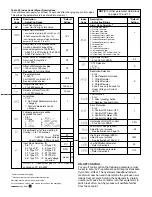
*Factory set before shipping.
**Process alarms are at fixed temperature points.
Deviation alarms move with set point value.
For convenience, values used can be recorded on the next page.
Long Scroll
Index
Description
*Default
Code
—Adjusting Range
Setting
Alarm Mode Selection**
0: Process High Alarm
1: Process Low Alarm
2: Deviation High Alarm
3: Deviation Low Alarm
2
4: Inhibited Process High Alarm
5: Inhibited Process Low Alarm
6: Inhibited Deviation High Alarm
7: Inhibited Deviation Low Alarm
8: Outband Alarm
9: Inband Alarm
10: Inhibit Outband Alarm
11: Inhibit Inband Alarm
12: Alarm Relay OFF as Dwell Time Out
13: Alarm Relay ON as Dwell Time Out
Hysteresis of Alarm
– 0 to 20.0% of SPAN
0.5
°C/°F Selection
– 0 to 1
0
0:°F, 1:°C
Resolution Selection
– 0 to 3
0: No Decimal Point Used
1: 1 Digit Decimal
2: 2 Digit Decimal
0
3: 3 Digit Decimal
2 and 3 can only be used for
Linear Voltage or Current
(IN=10)
Control Action
– 0 to 1
0: Direct (cooling) Action
1
1: Reverse (heating) Action
Error Protection
– 0 to 3
0: Control OFF, Alarm OFF
1: Control OFF, Alarm ON
1
2: Control ON, Alarm OFF
3: Control ON, Alarm ON
Hysteresis of ON-OFF control
– 0 to 20.0% of SPAN
0.5%
Low Limit of Range (SPAN)
Adjust for your process
–58
– See Instructions on Page 13.
High Limit of Range (SPAN)
Adjust for your process
1832
– See Instructions of Page 13
Low Calibration parameter
– Refer to Section 6.
32
High Calibration parameter
– Refer to Section 6.
1112
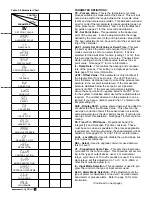
Index
Description
*Default
Code
—Adjusting Range
Setting
Set Point of control
SV
– Low Limit to High Limit Value
Alarm Set Point Value
– Low limit to high limit (If ALAI=0,1,4 or 5)
–0-3600 minutes (If ALAI=12 or 13)
18°F
–Low limit minus set point high limit minus
set point (IF ALAI=2, 3, 6 or 11)
Ramp Rate for the process value.
Limits an abrupt change of the
process temperature. (Soft start)
– 0-360°F 0-200°C/minute (If in=0-90)
0.0
– 0-3600°/minute (If in = 10)
Offset Value for Manual Reset
Only used if integral is 0.
0.0
– 0 to 100%
Offset shift for process value
– 199 count to 199 count
0.0
See page 18 for instructions
Proportional Band
0 - 360°F
For ON-OFF control set to 0
18.0
See instructions below.
Integral (Reset) Time, TI
– 0 to 3600 seconds
120 sec.
Derivative (Rate) Time, TD
– 0 to 1000 seconds
30 sec.
Local Mode
– 0 to 1-
0: No Control Parameters can be
1
changed.
1: Control Parameters can be
changed.
Following parameters will be
upgraded to Level 1
– 0 to 7
0: None
4:
0
1:
5:
2:
6:
3:
7:
Proportional Cycle Time, Heating &
Cooling – 0 to 120 seconds
Relay
20
3-32VDC Pulsed Voltage
1
Linear Voltage, 4-20ma Current
0
Input Mode Selection, IN
– 0 to 10
5: R Type T/C
T/C
0
0: J Type T/C
6: S Type T/C
1: K Type T/C
7: N Type T/C
RTD
8
2: T Type T/C
8: PT100 DIN
3: E Type T/C
9: PT100, JIS
4: B Type T/C
10: Linear Voltage
Linear 10
or Current
NOTE: T/C - Close solder gap G5. RTD - Open G5
Located on P.C.B. A909F
Table 5.3 Index Code (Menu) Descriptions:
(Do not disconnect power for at least 12 seconds after changing any control values.
This allows the parameters to be entered into memory.)
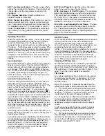
ON-OFF CONTROL:
For on-off control action the following parameters must
be set to zero (0): Proportional band, Integral, Derivative,
Cycle time, Offset. The hysteresis (deadband) adjust-
ment must now be used to determine the process oscil-
lations from set point. Setting the hysteresis to a larger
number will cause the contactor (or other equipment, to
switch less often, but the process will oscillate farther
from the set point.
NOTE: Further parameter definitions
on pages 12 and 13

