–
+
Thermocouple
Internal
Relay
1
2
3
4
5
6
7
8
9
10
Fuse
5A
Heater
3 Amps
Maximum
360W/120V
720W/240V
Maximum
Heater
Load
Incoming
Power
Red
–
+
Thermocouple
1
2
3
4
5
6
7
8
9
10
Control
Fuse
1A
Control
Power
1
2
3
4
+
Solid State
Relay
Heaters
+
–
Red
This diagram can also be used
for controls with 4-20mA output.
Heater
Fuse
Heater
Power
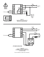
Figure 4.4
Example of wiring connections for
ETR-9090-122 with Relay Output.
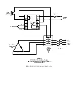
Figure 4.5
Example of wiring connections for
ETR-9090-132 with Pulsed Voltage Output
for Solid State Relay
B
B
A
3
4
5
RTD Sensor Connections
Note control label for incoming power requirements.
CAUTION
SHOCK
HAZARD

