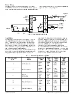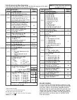
There are 5 levels of parameter security protection.
They are shown below in the order of protection.
Also refer to table 5.2 on page 10.
LEVEL 1
LOCL = 0 No changes can be made
LEVEL 1
LOCL = 1 Only set point can be changed
LEVEL 2
LOCL = 1 Long scroll at Process Valve
LEVEL 3
LOCL = 1 Long scroll at
LEVEL 4
LOCL = 1 Long scroll at
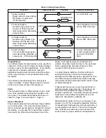
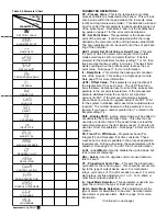
Table 5.5 Tuning Guide
ADJUSTMENT SEQUENCE:
SYMPTOM:
SOLUTION:
1.) Proportional Band
Slow Response
Decrease Proportional Band (Pb)
High Overshoot or Oscillations
Increase Proportional Band (Pb)
2.) Integral Time (Reset)
Slow Response
Increase Reset (i.e. Decrease Integral Time)
Instability or Oscillations
Decrease Reset (i.e. Increase Integral Time)
3.) Derivative Time (Rate)
Slow Response or Oscillations
Decrease Rate (i.e. Decrease Derivative Time)
High Overshoot
Increase Rate (i.e. Increase Derivative Time)
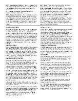
Table 5.6 Parameter Lockout
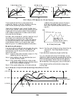
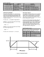
RAMP RATE ADJUSTMENT
The purpose of this adjustment is to control the rate at
which the process temperature can change. This feature
would be used when rapid temperature changes could
damage the product being controlled. When used, the
ramp rate is in effect at all times, during heat-up, set point
changes and cool-down.
The ramp rate (
) is expressed in degrees/minute
EXAMPLE 1: The process temperature cannot change
more than 5 degrees per minute.
Adjust =
5
EXAMPLE 2: The process temperature cannot change
more than 60 degrees per hour.
Adjust =
1
The ramp rate is not functional if is set to zero.
Manual Mode Operation:
It is suggested to use Manual Mode (open loop operation)
during the time the controller’s sensor is not functioning
and the control is unable to display the correct process
value. This can also be used when automatic control
(closed loop) is not possible or during the time required to
test the characteristics of a process.
In order to enter the manual mode operation press both
the “Scroll” key and the “Return” key for longer than 6
seconds and release. Now the control will display the out-
put percentage with a range of –100% to 100%. A posi-
tive value for heating output percentage and a negative
value for cooling output percentage. Press the UP or
DOWN key to adjust the output percentage. Zero output
percentage disables the heating output.
Ramp Rate
Ramp Rate
Set Point
Tempe
rature
TIME
Process Temperature
Figure 5.4 Ramp Rate Diagram

