Operating Procedure:
When the control has been wired, you can apply power.
The display will indicate the model number, software
version and LED lamp test. The temperature as
measured at the sensor should now be indicated by the
PV display. The thermocouple is wired in reverse if the
indicated temperature decreases as the temperature at
the thermocouple increases. The set point should be
lowered to a value (eg. 30°F) so the heaters will not be
energized. This will allow time to enter and make any
adjustments of the parameters. The process will not
heat-up.
Span Adjustment:
During this initial set-up, alarm points and any other set-
tings can now be made. The low limit and high limit
range settings (LLiE) and (HLiE) should be adjusted to
your process. This sets the range (SPAN) of the con-
trol. The set point cannot be adjusted out of this range.
For plastics processing and packaging, a span of 0-
800°F is common. If oils are used, a lower span such
as 0-300°F should be entered.
Automatic Tuning Procedure
When the settings have been made, you can return to
the PV/SV level. Do not enter the calibration level.
Adjust the required process temperature set point. The
green “output” lamp should turn on indicating the
heaters have been energized. You can auto-tune the
control to the set point by depressing the return ( )
button for six seconds, then release. This matches the
control’s PID values to your process requirements. The
lower decimal point will flash, indicating the control is in
the auto-tune mode. No other adjustments can be
made while the control is auto-tuning. During auto-tun-
ing, the process will take approximately twenty-five per-
cent longer to heat-up than it normally takes. After auto-
tuning, the correct PID values will be entered into the
control’s memory.
Auto-tuning will not function if the control has been con-
figured from PID to ON-OFF. For electric heating, PID is
usually recommended.
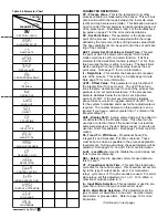
Auto-tuning may not give satisfactory results and hold a
close temperature on all applications. If this occurs, you
can change the PID values manually using the three
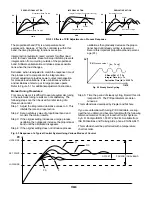
charts in Figure 5.1 on the top of the next page and
Table 5.5 for a guide. It is recommended to change
only one parameter at a time, so the results of that
change can be clearly noted.
ON-OFF Control:
On-off control action is recommended when continuous
cycling of the load cannot be used. Examples are
mechanical solenoids, large contactors and valves.
For on-off control, set the following parameters to zero:
proportional band; integral; derivative and offset
(oFSE). The hysteresis (hySE) adjustment is now used
to set the deadband. The larger the hysteresis is set,
the larger the deadband will be. A large deadband will
cause the contactor (or other device) to switch less
often, but the process will oscillate farther from the set
point. This setting is measured in degrees.
Adjusting PID Parameters:
The PID parameters can be reviewed by operating the
scroll key and noting whether the values are reason-
able or not. Examine the controller’s result. Modify the
PID parameters, if necessary, according to Table 5.5 on
page 15 until the control quality is acceptable.
PID Control
For various applications, the controller can be used as
P control only (set integral = 0, derivative - 0); PI con-
trol (set derivative = 0), PD control (set integral = 0),
and PID control.
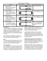
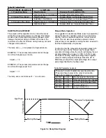
Figure 5.3 on page 14 represents the response of a
typical control system using various modes of control.
1.)
P control results in a response showing a devia-
tion (offset), a high overshoot and a moderate period of
oscillation. In addition, a significant length of time is
required before the system ceases to oscillate.
2.)
PI control has no offset, but elimination of offset
comes at the expense of higher overshoot, larger peri-
od of oscillation and a longer time required for
oscillations to cease compared with other modes of
control.
3.) PD control generally brings the system to steady
state in the shortest time with the lease oscillation.
However, it still has offset.
4.)
PID control is essentially a compromise between
the advantages of PI and PD control. Offset is elimi-
nated by the integral action. The derivative action
serves to lower offshoot and to eliminate some of the
oscillation realized with PI control.
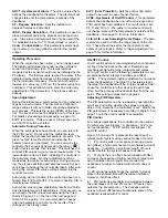
AHY1 - Hysteresis of Alarm - The value entered here
defines the deadband for the alarm. The alarm will not
change state until the temperature is outside of the
deadband.
CF - Degrees Selection - Sets the indication to
degrees Celsius or Fahrenheit.
rESO - Display Resolution - This parameter is used to
place a decimal point in the process and set point val-
ues. A two-place decimal point can only be used if the
“in” adjustment is set to 10; ;linear voltage or current.
ConA - Control Action - This parameter selects heat-
ing (reverse) or cooling (direct) action for the control
output.
ErPr - Error Protection - Sets the control and alarm
output to be used in case of sensor failure.
hYSE - Hysteresis of On-Off Control - This parameter
defines the deadband when on-off control is used and
PID control has been disabled. For on-off control, set
Pb, Ti and Td to 0. The output on a relay control will
not change state until the temperature is outside of the
deadband. Note page 13 for more information.
LLiE, HLiE - Low Scale/High Scale Range - The para-
meters are used to define the range (span) of the con-
trol. These should be set for the requirements and
safety of your process. Refer to “Span Adjustment” on
page 13 for further information.

