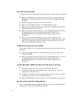
No serial console activity
If the serial console does not appear to be functioning correctly, check the following:
Make sure all PC/104 or PC/104
Plus
expansion cards are removed from the
XE–800 SBC. This ensures that other cards are not interacting with the XE–
800 SBC.
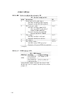
Remove the jumper from the “S” position at W1[1–2].
Make sure the COM1/2 connector on the XE–800 SBC is used.
Make sure a null modem adapter is installed between COM1 of the VTC-20F
cable and the serial port of your PC.
Make sure that your terminal emulator (such as HyperTerminal) on your PC is
set up properly. Refer to the Console devices chapter. Refer to the
HyperTerminal manual for information on setting up communication
parameters.
After verifying the above conditions, you can monitor voltage levels by
connecting an oscilloscope between the TxD* line on COM1 and ground. After
power-up, you should see a burst of activity on the oscilloscope screen. The
voltage level should switch b/–8V.
Garbled serial console screen activity
If you do get activity on your console screen but the message is garbled, check the
following:
Remove the jumper from the “S” position at W1[1–2] to ensure the default
settings for COM1.
Make sure that your terminal emulator (such as HyperTerminal) on your PC is
set up properly. Refer to the Console devices chapter. Refer to the
HyperTerminal manual for information on setting up communication
parameters.
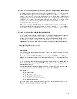
System generates a BIOS message but locks up when booting
Remove the jumper from the “S” position at W1[1–2] and reboot.
Verify that all the necessary boot files exist on the boot device. Copy any
missing files to the boot device.
If no files are missing, overwrite any files which may have become corrupted.
In addition, you may want to format the boot device.
Ensure the BIOS Setup settings match the actual configuration (see page 57.)
System will not boot from CompactFlash
Many CompactFlash devices as shipped from the factory are not bootable devices.
See page 53 to make your CompactFlash bootable.
92
Содержание XE-800
Страница 18: ...Figure 2 1 XE 800 SBC component diagram top 18 ...
Страница 19: ...Figure 2 2 XE 800 SBC component diagram bottom 19 ...
Страница 20: ...Figure 2 3 XE 800 SBC dimensions 20 ...
Страница 89: ...MOV AX 0fb0bh MOV DX 0ffffh INT 17h MOV aData AL if aData 1 printf U1 jumper is ON n 89 ...


