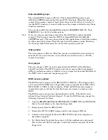
Extended BIOS jumper
The extended BIOS jumper is W1[3–4]. The extended BIOS memory region
(D8000h to DFFFh) contains the Octagon INT17 functions. When this jumper is
removed, this memory region is freed up for other uses. Note that if you want to
use the INT17 functions, you must either leave the jumper installed or copy those
functions elsewhere.
You can also modify the extended BIOS using the MAKEBIOS.BAT file. Type
MAKEBIOS ? for a list of available options.
Note
If you are using an operating system other than DOS the X jumper should be
removed. The X jumper maps the INT17 extended BIOS into the 0xD8000-
0xDFFFF memory. This can cause problems with applications or hardware running
on other operating systems if they attempt to use this memory range. Removing
the X jumper frees this memory for use by other operating systems.
Video jumper
The video jumper is W1[5–6]. When this jumper is installed the on-card video is
enabled. To use a serial console, or an extension-card video (such as a PC/104),
remove this jumper.
User jumper
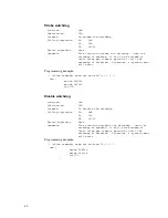
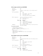
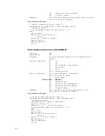
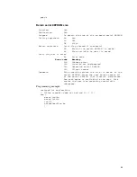
The user jumper is W1[7–8] and is associated with GPIO 23 of the Winbond
SuperIO controller. The INT17 functions provide an easy method to implement
software routines according to whether or not a jumper has been installed. Refer to
the INT17 calls to read user jumper on page 88.
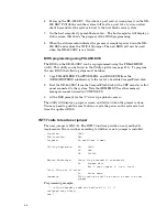
BIOS recovery jumper
The BIOS recovery jumper on the XE–800 SBC is W1[9–10]. This jumper allows
you to reinstall the BIOS from a floppy disk using a serial link from COM1 of the
XE–800 SBC to COM1 of a host computer. When the BIOS recovery jumper is
removed, the system will use the boot block recovery process to program a new
BIOS.
The BIOS recovery process uses the embflash.exe utility. This utility can be
obtained from Octagon Technical Support. To use the BIOS recovery jumper the
following steps must be taken:
1. Copy the EMBFLASH.EXE, PLATFORM.BIN, CLIENT.BIN, and BIOS.ROM
files to the root directory of a bootable floppy disk.
2. Remove power from the XE–800 SBC.
3. Remove the W1[9–10] BIOS jumper and the video jumper W1[5–6].
4. Connect a serial console between the XE–800 SBC and a host computer as
described on page 50.
5. Put the bootable floppy disk from step 1 with the embflash.exe and support
files in drive A of the host computer, and reboot the host computer from the
floppy drive.
87
Содержание XE-800
Страница 18: ...Figure 2 1 XE 800 SBC component diagram top 18 ...
Страница 19: ...Figure 2 2 XE 800 SBC component diagram bottom 19 ...
Страница 20: ...Figure 2 3 XE 800 SBC dimensions 20 ...
Страница 89: ...MOV AX 0fb0bh MOV DX 0ffffh INT 17h MOV aData AL if aData 1 printf U1 jumper is ON n 89 ...

