63
Basics
IMS-MN-LMDA42C_A.pdf
LMD CANopen
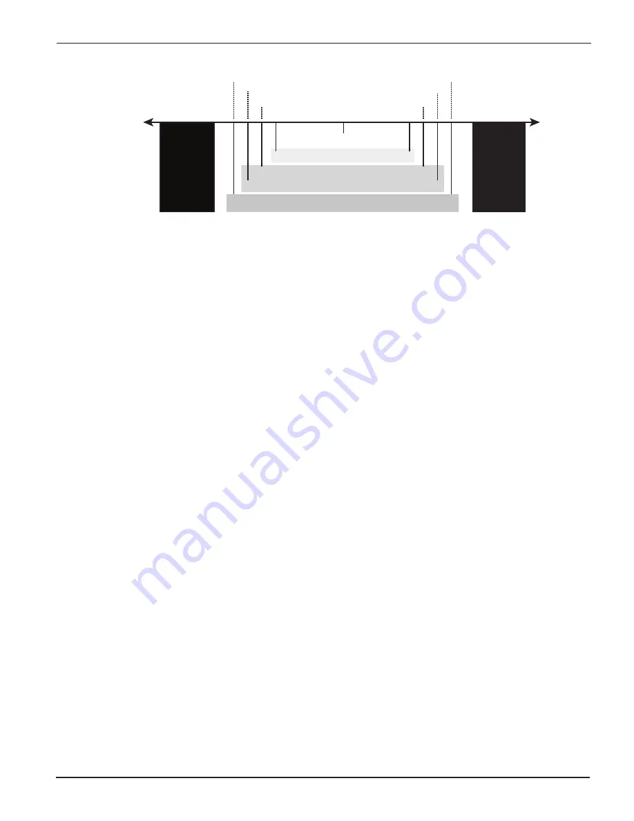
The following graphic shows the control bounds for hMT.
Stall zone
> 2 full steps
Stall zone
> 2 full steps
1.1
1.3
1.5
1.7
1.7
1.5
1.3
1.1
0
Best speed performance
Best overall performance
Best torque performance
hMT maintains the rotor/stator relationship
within the set control bounds
LEAD
LAG
Hybrid Motion Technology uses a high speed feedback loop to tightly maintain the rotor/stator
relationship within a specified range, or control bounds.
See the CANopen Fieldbus Manual Object 2702h for configuration options.
Variable Current Control
Historically stepper motor drivers operate at two adjustable current levels:
1. Running current, the current level in use when the shaft is moving.
2. Holding or reduction current, the current level in use when the shaft is at rest.
Variable current control uses hMT to accurately measure and track the rotor/stator relationship
and apply current as needed. An example of this can be seen when current is applied during
acceleration or deceleration, the current is reduced to the level required to move the load when
the axis is at velocity. This can lead to greater power efficiency and reduced motor operating
temperatures.
Position Make-up
When active, the position make-up function stores the difference between commanded pulses
and actual motor steps in a register. At the completion of the move the lead or lag pulses will
be reinserted into the profile and moved to the commanded position at one of two velocity
presets.
Overview of Motor Phase Current
NOTE:
LMD CANopen models without an encoder will operate in fixed run/hold current only!
The motor phase current of the drive is influenced by the following factors:
• The setting of the run current.
• The setting of the holding current.
• The setting of the holding current delay time.
• Current control defined as fixed or variable.


