21
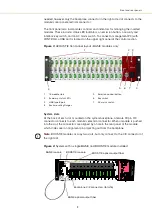
Front and rear panels
Figure 5
ACOUSTIK rear panel layout
Note:
Pin assignments of connectors are described in
Multiplexed optical outlet
FC/APC or SC/APC connector – this is an optional feature used when optical outputs
of the inserted modules are multiplexed onto a single optical output – see
“Multiplexed optical output” on page 18
. The majority of systems do not support this
feature and a metal covering plate is installed in its place.
LEMO connector
2 pin door interlock circuit – connect it to a door interlock circuit using the supplied
LEMO plug connector assembly, see
“Connecting the safety interlock” on page 35
.
Modulation and Trigger
Male D-sub 9 pin connector providing pins for wavelength input/output and trigger
signal connectivity for inserted BASIK modules, see
AC mains input
AC inlet - standard IEC C14 AC inlet connector
Ethernet
10/100 MBps BASE-T Ethernet port to connect CONTROL to the laser over IP – see
“Connecting a PC to the ACOUSTIK using Ethernet” on page 45
1
Multiplexed optical output – OPTIONAL
5
AC mains input
2
LEMO door interlock connector
6
10/100 BASE-T Ethernet port
3
External bus female D-sub 15 pin connector 7
Cooling fins
4
Modulation & Trigger I/O male D-sub 9 pin connector
1
2
4
5
6
3
7
Содержание Koheras ACOUSTIK
Страница 1: ...Item 800 633 01 Koheras ACOUSTIK PRODUCT GUIDE Multi Channel Modular Laser System...
Страница 10: ...10...
Страница 14: ...14...
Страница 16: ...16...
Страница 26: ...System labels 26...
Страница 28: ...28...
Страница 34: ...Operating and storage environment 34...
Страница 42: ...42...
Страница 78: ...Module overview 78...
Страница 80: ...80...
Страница 82: ...82 Figure 44 Mechanical dimensions 483 00 45 00 302 50 4 50 125 00 2...
Страница 92: ...Installing CONTROL 92...
Страница 95: ......
Страница 96: ...1 Koheras ACOUSTIK Product Guide Revision 1 0 09 2021 W 10456...

