85
C Interface Pin Assignments
Modulation input/output
The Modulation input/output interface on the laser is a male D-sub 9 pin
connector. The pin assignments are described in
.
Table 11
Modulation connector pin assignment
External bus
The External bus connector on the rear panel of the laser is a female D-sub 15 pin
connector. The pin assignments are described in
.
Table 12
External bus pin assignment
Pin #
Signal
Description
1
Trigger
Logic input/output for either control or indication of laser emission.
Active high. See Trigger for more information.
2
GND
0 volt ground
3
Amplitude-
Negative branch of differential input/output for amplitude
modulation.
4
AGND
0 volt analog ground for modulation signals
5
Wavelength-
Negative branch of differential input/output for wavelength
modulation.
6
GND
0 volt ground
7
Am
Positive branch of differential input/output for amplitude modulation.
8
AGND
0 volt analog ground for modulation signals
10
Wav
Positive branch of differential input/output for wavelength
modulation.
Pin #
Signal
Description
1
NC
Not connected
2
RS485-
The negative/inverted link of the RS485 communication signal.
3
Interlock loop+
Positive connection of the interlock loop. Must be connected to
Interlock loop- (pin no. 4) to enable laser emission from the system.
4
Interlock loop-
Negative connection of the interlock loop. Must be connected to
Interlock loop+ (pin no. 3) to enable laser emission from the system.
5
Emission
Collector output with an internal 270 Ω resistor in series.Outputs a
logic high when the Koheras ACOUSTIK system has laser emission
ON. To indicate emission with an LED, its anode can be connected
directly to this pin and its cathode connected to the GND (pins 5,6,
13 or 14).
10
RS485+
The positive/non-inverted link of the RS485 communication signal.
11
Not in use
For future use, do not connect anything to this pin.
Содержание Koheras ACOUSTIK
Страница 1: ...Item 800 633 01 Koheras ACOUSTIK PRODUCT GUIDE Multi Channel Modular Laser System...
Страница 10: ...10...
Страница 14: ...14...
Страница 16: ...16...
Страница 26: ...System labels 26...
Страница 28: ...28...
Страница 34: ...Operating and storage environment 34...
Страница 42: ...42...
Страница 78: ...Module overview 78...
Страница 80: ...80...
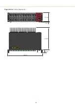
Страница 82: ...82 Figure 44 Mechanical dimensions 483 00 45 00 302 50 4 50 125 00 2...
Страница 92: ...Installing CONTROL 92...
Страница 95: ......
Страница 96: ...1 Koheras ACOUSTIK Product Guide Revision 1 0 09 2021 W 10456...


