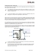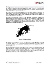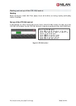
This document may be subject to change
Side 15 of 24
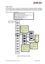
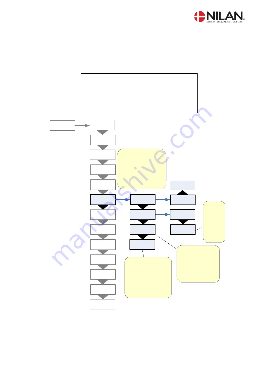
Temp. control
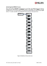
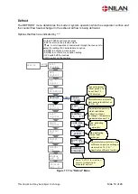
The temperature sensor to be used to control the system is selected in the TEMP. CONTROL
menu. It is also possible to stipulate a minimum temperature at which the system is to be stopped
to prevent further cooling of the building if the primary heating system has cut out for some reason.
Options that flash are indicated by
” ”
On the CTS602 control panel, press:
- ESC to return to the previous menu
-
p
to scroll upwards or downwards through the menus or to
adjust the setting of an activated menu option
- ENTER to activate a menu option
- ENTER to confirm a menu option setting
- OFF switch off the controls
- ON to switch on the controls
DATALOG
INTV 10
HEAT
SURFACE
INLET
HEATING
TEMP.
CONTROL
ENTER
AIR
EXCHANGE
DEFROST
INLET
CONTROL
SERVICE
ENTER
RESTART
OFF
MANUAL
OFF
PRESET
OFF
ROOM
CONTROL
EXTERNAL
-1°C
AIR
QUALITY
Option for an extra heating
element via relay output,
R8. R8 is an accessory and
the option is only possible
via accessory pcb.
The temperature is added
or subtracted to/from the
set point shown in the main
menu.
Determines the sensor to be
used for control purposes:
PANEL: T15 (in control panel)
EXTERNAL: T10 (Duct sensor
If T15 is chosen as the
controlling sensor the sensor
follows ROOM LOW this
temperature.
SENSOR
PANEL
SENSOR
”PANEL”
PRIORITY
”HP”
PRIOR.
”OFF”
ENTER
ENTER
ROOM
LOW 10°C
PRIORITY
HP
Stops the system at this
room temperature (20-
1°C, -- indicates that the
function is inactive). The
”--” setting should be
used if the control panel
is installed in a cold
location.
OFF:
ventilation
without heat
pump.
VP:
ventilation
with only
heat pump
active.
MODBUS
ADR 30
SENSOR
”EXTERNAL”
Figure 12: The "Temp. control" Menu


