


Table of contents
Table of contents ............................................................................................................................ 2
Figure table .................................................................................................................................... 2
Introduction ..................................................................................................................................... 3
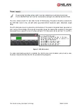
Power supply .................................................................................................................................. 4
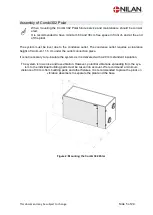
Assembly of Combi 302 Polar......................................................................................................... 5
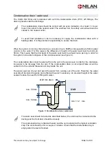
Condensation drain / water seal ..................................................................................................... 6
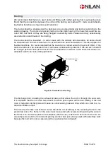
Ducting ........................................................................................................................................... 7
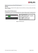
Starting and set up of the CTS 602 control ..................................................................................... 8
Starting ....................................................................................................................................... 8
Set up of the CTS 602 control ..................................................................................................... 8
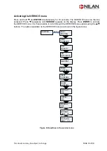
Activating the SERVICE menu .................................................................................................... 9
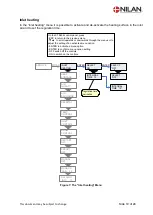
Inlet heating .............................................................................................................................. 10
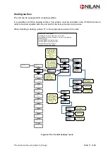
Heating surface ......................................................................................................................... 11
Air quality .................................................................................................................................. 12
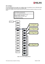
Air exchange ............................................................................................................................. 13
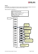
Defrost ...................................................................................................................................... 14
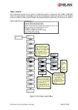
Temp. control ............................................................................................................................ 15
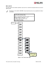
Inlet control ............................................................................................................................... 16
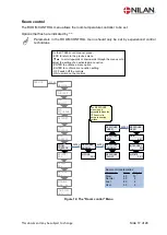
Room control ............................................................................................................................ 17
Restart ...................................................................................................................................... 18
Preset ....................................................................................................................................... 19
Manual ...................................................................................................................................... 20
Modbus ..................................................................................................................................... 21
Datalog ..................................................................................................................................... 22
System dimension ........................................................................................................................ 23
Accessories / spare parts ............................................................................................................. 24
Figure table
Figure 1: CTS 602 control ............................................................................................................... 4
Figure 2: Mounting the Combi 302 Polar ........................................................................................ 5
Figure 3: Condensation drain / water seal....................................................................................... 6
Figure 4: Insulation of ducting ......................................................................................................... 7
Figure 5: CTS 602 control ............................................................................................................... 8
Figure 6: Headlines in the service menu ......................................................................................... 9
Figure 7: The "Inlet heating" Menu................................................................................................ 10
Figure 8: The “Central heating” menu ........................................................................................... 11
Figure 9: The "Air quality" Menu ................................................................................................... 12
Figure 10: The "Air exchange" Menu ............................................................................................ 13
Figure 11: The "Defrost" Menu ..................................................................................................... 14
Figure 12: The "Temp. control" Menu ........................................................................................... 15
Figure 13: The "Inlet control" Menu............................................................................................... 16
Figure 14: The "Room control" Menu ............................................................................................ 17
Figure 15: The "Restart" Menu ..................................................................................................... 18
Figure 16: The "Preset" Menu ....................................................................................................... 19
Figure 17: The "Manual" Menu ..................................................................................................... 20
Figure 18: The "Modbus" Menu .................................................................................................... 21
Figure 19: The "Datalog" Menu ..................................................................................................... 22
Figure 20: System dimension ....................................................................................................... 23