


2-1
Contents
1.
System Configurations and Part Names............................................................................................ 2-3
1.1
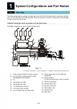
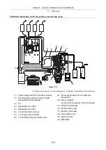
Overview ........................................................................................................................................ 2-3
1.2
Optical Paths of Lasers .................................................................................................................. 2-5
1.2.1
Laser Unit........................................................................................................................... 2-5
1.2.2
Microscope Part (TIRF-PAU Illuminator and Ti-E System)................................................ 2-6
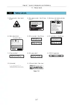
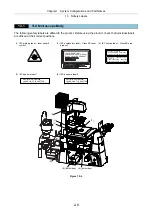
1.3
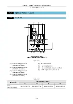
Safety Labels.................................................................................................................................. 2-7
1.3.1
Ti-U Microscope Body........................................................................................................ 2-8
1.3.2
Ti-E Microscope Body........................................................................................................ 2-9
1.3.3
LU4A Four-laser Module A (with LU4-B5 Beamsplitter 50/50 installed)............................. 2-10
1.3.4
LU-LR Four-laser PS Rack .............................................................................................. 2-11
1.3.5
TI-LU4SU Shutter Unit LU4 ............................................................................................. 2-12
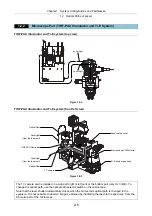
1.3.6
TIRF-PAU Illuminator ....................................................................................................... 2-13
1.4
Name of Each Part....................................................................................................................... 2-14
2.
Preparations........................................................................................................................................ 2-25
2.1
Check Items and Tools ................................................................................................................. 2-25
2.2
Overview of Setup Procedure ...................................................................................................... 2-26
3.
Setting Up the PC and Operation Software ..................................................................................... 2-27
4.
Setting Up the Microscope ................................................................................................................ 2-28
4.1
Overall Configuration ................................................................................................................... 2-28
4.2
Setup Procedure .......................................................................................................................... 2-29
4.2.1
Assembling Each Part and Attaching Them to the Microscope....................................... 2-29
4.2.2
Attaching the Laser Safety Kit.......................................................................................... 2-37
4.2.3
Attaching the Stage Up Kit ............................................................................................... 2-39
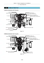
4.2.4
Attaching the Back Port Unit ............................................................................................ 2-42
5.
Laser Unit ............................................................................................................................................ 2-44
5.1
Overview of the Laser Units ......................................................................................................... 2-45
5.1.1
LU4A Four-laser Module A (with LU4-B5 Beamsplitter 50/50 installed) .......................... 2-45
5.1.2
LU-LR Four-laser PS Rack .............................................................................................. 2-49
5.2
Installation of the LU4-B5 Beamsplitter 50/50 (TIRF-PAU system) ............................................. 2-51
5.2.1
Preparation....................................................................................................................... 2-51
6.
Connection between the Laser Unit and the Microscope .............................................................. 2-56
6.1
Setting and Connecting the TI-LU4SU Shutter Unit LU4 ............................................................. 2-56
6.2
Attaching the Optical Fiber to the Light Source ........................................................................... 2-59
6.3
Replacement of Optical Path Switch Mirror ................................................................................. 2-61
6.4
Cable Connections (Four Laser Module A).................................................................................. 2-63
7.
Confirmation and Check Sheet ......................................................................................................... 2-64
7.1
Checking Procedure..................................................................................................................... 2-64
7.2
Check Sheet................................................................................................................................. 2-65
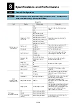
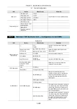
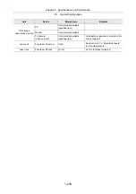
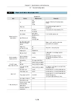
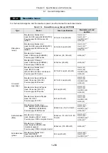
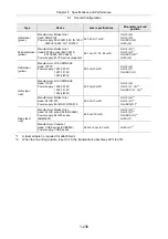
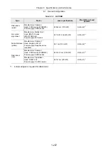
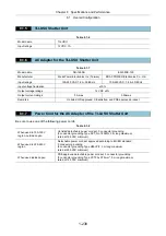
8.
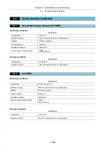
Specifications and Performance....................................................................................................... 2-67
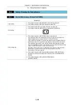
8.1
Overall Configuration ................................................................................................................... 2-67
Содержание Eclipse Ti Series
Страница 2: ......
Страница 13: ...Part 1 For Setting Up TI TIRF TI TIRF E or TI PAU Series Setup Manual For Authorized Nikon Personnel ...
Страница 14: ......
Страница 256: ......
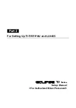
Страница 257: ...Part 2 For Setting Up TI TIRF PAU and LU4 B5 Series Setup Manual For Authorized Nikon Personnel ...
Страница 258: ......
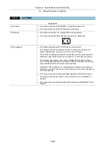
Страница 260: ...Contents 2 2 8 2 Environmental Conditions 2 70 8 3 Safety Standards Compliance 2 71 ...


