


Chapter 5 Laser Unit
5.5 Setting Up the LU-LR Four-laser PS Rack
1-210
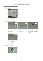
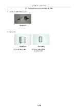
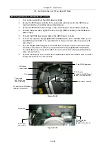
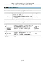
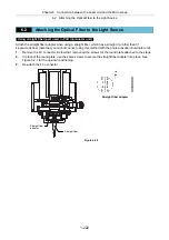
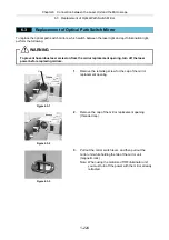
Mounting DPSS laser (85BCD/85YCA series)
1.
Turn on the key switch of the DPSS laser controller.
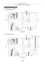
2.
Secure the DPSS laser controller in the position [4] with screws. (Fix the DPSS laser
controller directly to the bottom plate without clamps.)
3.
Secure the DPSS laser power supply in the position [5] with the provided clamps [3].
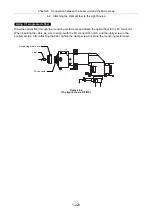
4.
Connect the power cable [8] (85YCA-561nm) or [9] (85BCD-488nm) to the DPSS laser
power supply.
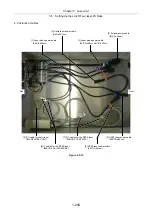
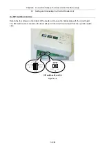
5.
Connect the DPSS laser power cable to the DPSS laser controller.
6.
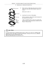
Connect the interlock cable [6] (85BCD/YCA INTERLOCK) to the "INTERLOCK" port of
the DPSS laser controller. (The specifications of the two interlock cables are same with
each other.)
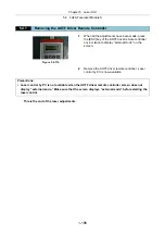
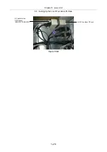
7.
Connect the [INTERLOCK] port of the DPSS laser controller and the control box of the
LU-LR four-laser PS rack with the provided RS232C cable [7] (85BCD/YCA RS232C).
The cable [7] can be connected to either of the two connectors whose specifications are
same with each other.
8.
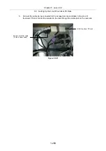
Connect the cable (to be connected to the DPSS laser head) to the DPSS laser controller
through the cable port on the rear side.
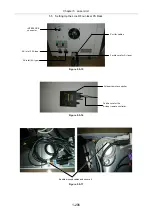
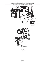
Figure 5.5-22
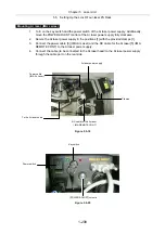
Figure 5.5-23
To the DPSS laser head
RC cable for the DPSS laser
(85BCD/YCA RS232C)
DPSS IT cable
(IT cable for the DPSS laser)
(85BCY/YCA INTERLOCK)
Clamp
DPSS laser
power supply
DPSS laser controller
Key switch
Power cable
(85YCA-561nm)
(85BCD-488nm)
RC cable for the
DPSS laser
(85BCD/YCA RS232C)
DPSS laser
power cable
Содержание Eclipse Ti Series
Страница 2: ......
Страница 13: ...Part 1 For Setting Up TI TIRF TI TIRF E or TI PAU Series Setup Manual For Authorized Nikon Personnel ...
Страница 14: ......
Страница 256: ......
Страница 257: ...Part 2 For Setting Up TI TIRF PAU and LU4 B5 Series Setup Manual For Authorized Nikon Personnel ...
Страница 258: ......
Страница 260: ...Contents 2 2 8 2 Environmental Conditions 2 70 8 3 Safety Standards Compliance 2 71 ...


