


Chapter 5 Laser Unit
5.3 C-LU3EX Three-laser Unit EX
1-135
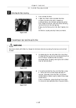
7
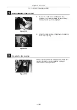
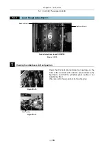
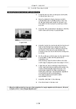
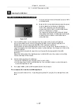
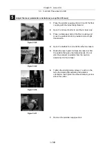
Adjusting the AOM unit
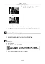
Figure 5.3-33
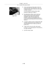
1.
Loosen the X-axis, Z-axis, and rotation clamp screws
on the AOM unit.
2.
Open the laser shutter, and adjust along the X-and
Z-axes so that the laser beam passes through the
AOM opening. Then, turn off the power for the AOM
controller to pass the 0th-order light.
To adjust in the Z-axis direction, use the adjusting
screw with the clamp screw completely loosened.
The transmission ratio of after-AOM to pre-AOM
should be approximately 95%.
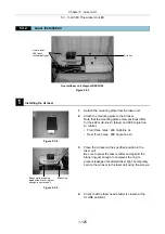
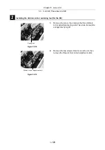
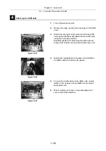
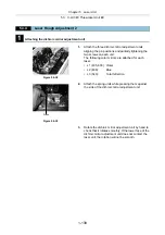
Figure 5.3-34
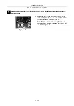
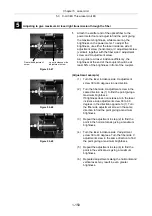
3.
Detach the laser unit front sheet metal cover.
4.
Turn off the AOM controller [REMOTE] switch.
(If the [REMOTE] switch is in the ON position, the
AOM controller will be turned on automatically when
the PC is turned on. If the [REMOTE] switch is in the
OFF position, the AOM controller can be turned on
or off independent of the PC.)
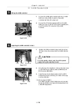
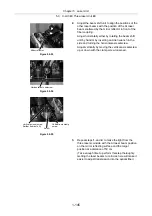
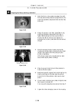
Rotation adjuster screw
X-axis clamp screw
Z-axis clamp screw
Rotation clamp screw
X-axis clamp screw
Z-axis adjuster
screw (setscrew)
Содержание Eclipse Ti Series
Страница 2: ......
Страница 13: ...Part 1 For Setting Up TI TIRF TI TIRF E or TI PAU Series Setup Manual For Authorized Nikon Personnel ...
Страница 14: ......
Страница 256: ......
Страница 257: ...Part 2 For Setting Up TI TIRF PAU and LU4 B5 Series Setup Manual For Authorized Nikon Personnel ...
Страница 258: ......
Страница 260: ...Contents 2 2 8 2 Environmental Conditions 2 70 8 3 Safety Standards Compliance 2 71 ...


