


Chapter 5 Laser Unit
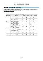
5.4 LU4A Four-laser Module A
1-190
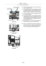
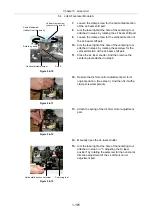
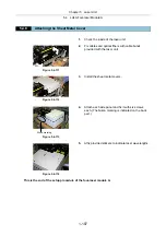
Figure 5.4-94
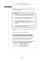
6.
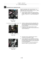
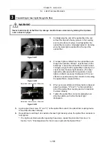
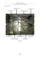
Rotate the adjustment screws "H" and "V" at the
optical fiber side to maximize the laser intensity.
7.
Repeat Step 5 and Step 6 to maximize the laser
intensity.
2
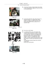
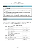
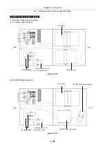
Attaching the fiber coupling
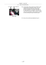
Figure 5.4-95
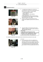
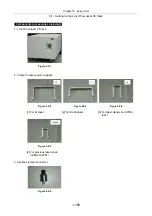
Figure 5.4-96
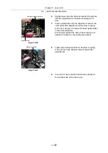
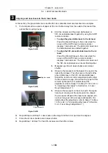
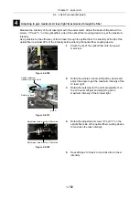
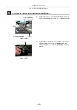
1.
Close all laser shutters.
2.
Attach the optical fiber coupling device. The tool hole
must face upward and the key groove must be on
the right viewed from the front side of the fiber
coupling device. Tighten three screws to fix it.
Adjustment screw on the H fiber side
Adjustment screw on the V fiber side
Tool hole
Key groove
Содержание Eclipse Ti Series
Страница 2: ......
Страница 13: ...Part 1 For Setting Up TI TIRF TI TIRF E or TI PAU Series Setup Manual For Authorized Nikon Personnel ...
Страница 14: ......
Страница 256: ......
Страница 257: ...Part 2 For Setting Up TI TIRF PAU and LU4 B5 Series Setup Manual For Authorized Nikon Personnel ...
Страница 258: ......
Страница 260: ...Contents 2 2 8 2 Environmental Conditions 2 70 8 3 Safety Standards Compliance 2 71 ...


