IV Connecting and Installing the Equipment
3 Connection Methods
- 13 -
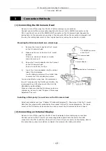
Vertical tube of microscope
To CAMERA connector
on the DS-L1
DS camera head
C mount adapter
C mount
3
Connection Methods
(1) Connecting the DS Camera Head
Be sure to turn off the power for the DS-L1 before making any connections.
Connect one end of the camera cable supplied with the unit to the CAMERA connector on the
DS-L1 and the other end to the CAMERA OUT connector on the DS camera head. Squeeze the
locking tabs on the connector as you plug in the connector. When the connector is plugged in all
the way, the locking tabs return to their original positions, locking the connector in place.
Mounting the DS camera head on a microscope
1)
Remove the C mount cap from the C mount
on the DS camera head.
2)
Make sure there is no dust on the C mount
adapter.
If there is, use an air blower or similar
means to remove it.
3)
Screw the C mount adapter into the C mount
on the DS camera head.
Screw it in as far as it will go.
4)
Insert the C mount adapter into the vertical
tube of the microscope.
Use the clamping screw on the vertical tube
to secure the C mount adapter in place.
You can also attach a relay lens. We recommend
the x0.7 relay lens for the DS-5M and DS-5Mc. We
recommend the x0.55 relay lens for the DS-2Mv,
DS-2MBW, and DS-2MBWc.
When you have mounted the DS camera head on a
microscope, be sure to read "Chapter V Microscope
Adjustment" as well.
Installing a third-party C mount lens on the DS camera head
Select a mountable lens (see "Chapter II Peripheral Equipment"), then screw it into the C mount.
Note that the image quality produced by this product is tuned for microphotography. The tripod
mount on the DS camera head can also be used to mount the DS camera head on a tripod.
(2) Connecting an External Display
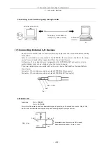
Be sure to turn off the power for the DS-L1 and the display before making any connections.
Connect one end of the D-sub 15-pin connecting cable supplied with the unit to the RGB
connector on the DS-L1 and the other end to the D-sub 15-pin connector on the display. Secure
the connections, using a screwdriver to tighten the screws on the cable connectors.
Содержание DS-2MBW
Страница 2: ......
Страница 9: ...CONTENTS vii 3 DS Remote Controller DS RC 169 4 DS AC adapter 170 5 Overall Specifications 170 ...
Страница 10: ......


