Height Rider/SP Series
Operating & Safety Instructions
English/USA – 01/18
Original instructions
65
A6
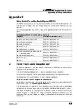
PREVENT MOVEMENTS OF LOAD HOLDING CYLINDERS IN CASE OF PIPE
FAILURE
The load holding system is PL c in accordance to with BS EN ISO 13849-1:2015 as required by BS EN
280:2013+A1:2015
1.
The limits of the safety-related parts to the category selected and any fault exclusions;
The load holding system comprises of a load holding device mounted to the cylinder.
2.
The limits of the SRP/CS and any fault exclusion, for which, when essential for maintaining the
selected category or categories and safety performance, appropriate information (e.g. for
modification, maintenance and repair) shall be given to ensure the continued justification of the
fault exclusion(s);
Do not alter, modify or disable in any way the controls, safety devices, interlocks or any other part of
the machine.
In the event of a hose failure ensure a recovery plan is in place that does not require the movement of
the affected cylinder. A safe route of recovery might involve the replacement in-situ of the failed hose
before further movement of the machine is possible.
Maintenance must only be carried on by appropriately trained and competent persons.
3.
The effects of deviations from the specified performance on the safety function(s);
If the load holding system of the product does not function as intended the angle of the booms may not
be maintained.
If the angle of cage is not maintained there is an increased risk of ejection of tools and equipment from
the cage;
In the event of the operator or other occupants of the cage not using the required safety equipment they
may be ejected from the cage and serious injury or death may occur.
There is a load holding device contained within the assembly of the slave levelling cylinder such that if
a hose fails the cage position is maintained until the operator can be recovered from the cage.
4.
Clear descriptions of the interfaces to the SRP/CS and protective devices;
The load holding system comprises of a pilot operated over centre valve on each load holding cylinder.
The opening of the load holding valve is dependent on the application of a pilot pressure in the descent
line to bring the machine down. Excessive over pressure either by overload or thermal expansion can
induce an over centre pilot descent until the excess pressure condition is removed.
5.
Response time
The load holding system is a direct acting hydraulic system and as such the response time is near
instantaneous.
Содержание HR 12
Страница 77: ......


