26
CHECK AND ADJUSTMENT PROCEDURES
:
Drilling Check and Adjustment
1) Load the drilling confirmation shape data and process a lens.
Use the standard o0.8 drill bit.
2) Check the hole diameter.
It is normal when the diameter of hole (9) becomes 2.0 ±0.1 mm.
3) Check the hole depth.
Check the depths of holes (1) to (3). It is normal when hole (3) is drilled and hole (2) is slightly
made on the lens surface.
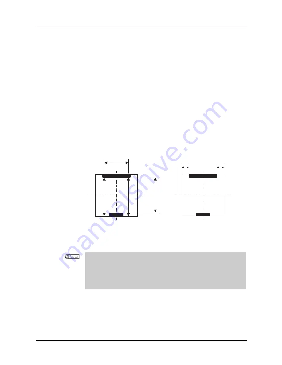
4) Check the hole/slot reference, drill zero point, and drill hole vertical position.
Check the hole/slot reference, drill zero point, and drill hole Vertical position at the holes (4) to (6)
and (10) to (12).
• Hole/slot reference: It is normal when the difference between A and B in the figure below is within
0.1 mm.
• Drill zero point: It is normal when the difference between C and D in the figure below is within 0.1
mm.
• Drill hole vertical position: It is normal when the L in the figure below is 37.0 ±0.1 mm.
5) Check the front surface offset.
It is normal when holes (7) and (8) are drilled in the same position on the lens front surface.
19
L
A
B
C
D
• Adjustment is necessary when the specified values are not obtained.
See “3.6.2 Adjusting the hole diameter” (page 27).
See “3.6.3 Adjusting the hole depth” (page 28).
See “3.6.4 Adjusting the hole/slot reference, drill zero point, and drill hole vertical position” (page
29).
See “3.6.5 Adjusting the front surface offset” (page 31).
Содержание ME 1200
Страница 6: ...IV ...
Страница 10: ...2 REQUIREMENTS Requirements ...
Страница 58: ...50 CHECK AND ADJUSTMENT PROCEDURES Clock Check ...


