Nidek Medical ICE mini Скачать руководство пользователя страница 74

64

CONNECTION AND SETTINGS

Parameter Settings

z

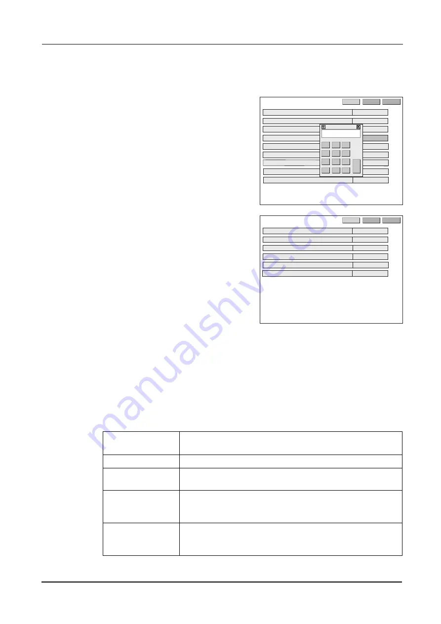
For the parameters whose settings must be specified by values, the numeric keypad is dis-
played.

1) Enter a value with the numeric keypad.

2) Press the Ent button to confirm the entry.

To cancel the entry, press the CE button.

3) The numeric keypad closes.

3

Press the >> button to go to the Parameter 2
screen and change the desired parameter set-
tings in the same manner.

4

Go back to the layout screen.

Press the EXIT button.

[Parameter description: Parameter 1 screen]

1)  System: Blocker/LE, Mini LAB, Blocker LAB, VCA (Preset), VCA (Auto)

Factory setting: Blocker/LE

Sets the system configuration so that the ICE mini can be connected.

2CTCOGVGT

/KPK.#$

':+6

'0).+5*

56&

5[UVGO

45%$CWFTCVG

%WR/QFG

(WNNG[G/KPKOWO5K\G

)TKPF/KPKOWO5K\G*

)TKPF/KPKOWO5K\G8

)TQQXG&GRVJ

)TQQXG9KFVJ

.CPIWCIG


+%'OKPK㧦ޓ8غغޓޓ

'PV

%'

2CTCOGVGT

':+6

.'


6'0-';

.C[QWV2TGUGV

#NKIOGPV5ECNG2KVEJ

#NKIOGPV/CTM85K\G

2QNKUJ5$5GVVKPI

+PRWV+PVGTHCEG,1$260%QFG

&KURNC[CWVQQHHVKOGOKP

Blocker/LE

Smallest system comprised of the ICE mini directly connected to the LE-
9000SX (maximum of two units)

Mini LAB

Small- or middle-scale system where the ICE mini acts as a data server

Blocker LAB

System connecting the ICE mini and server PC via a LAN port.

The communication protocol is NIDEK-LAN.

VCA (Preset)

System using the RS-232cable via the Edger 1 port to connect the ICE 
mini and Preset Initialization type VCA server PC.

The communication protocol is VCA.

VAC (Auto)

System using the RS-232cable via the Edger 1 port to connect the ICE 
mini and Auto Initialization type VCA server PC.

The communication protocol is VCA.

Содержание ICE mini

Страница 1: ...INTELLIGENT BLOCKER Model ICE mini OPERATOR S MANUAL...

Страница 2: ...nkyo Ku Tokyo 113 0033 Japan Telephone 81 3 5844 2641 Facsimile 81 3 5844 2642 NIDEK INCORPORATED 47651 Westinghouse Drive Fremont California 94539 U S A United States Agent Telephone 510 226 5700 Fac...

Страница 3: ...ument Keep this manual handy for verification If you encounter any problems or have questions about the software please contact NIDEK or your authorized distributor In this manual a signal word is use...

Страница 4: ...ion requirements If the line voltage is too high or too low the instrument may not perform properly Mal function or fire may occur Connect the power plug to a ground outlet Or connect a grounding wire...

Страница 5: ...k or fire In the event of malfunction disconnect the power cord from the wall outlet Never touch the inside of the instrument and contact NIDEK or your authorized distributor Never press the LCD touch...

Страница 6: ...Maintain the surrounding temperature and humidity at the following ranges during transport and storage of the instrument Environmental conditions Temperature 20 to 60 C Humidity 10 to 95 Non condensi...

Страница 7: ...enance work area CAUTION Follow the local ordinances and recycling regulations regarding disposal or recycling of the components It is recommended to commission the disposal to a designated industrial...

Страница 8: ...VI...

Страница 9: ...t and VCA Auto systems 28 2 2 4 Saving Data 29 2 2 5 Blocking with frame change holder 30 2 2 6 Blocking with sheet 31 2 3 Setting Processing Conditions and Entering Lens Layout Data 32 2 3 1 Setting...

Страница 10: ...nnection 67 4 2 1 Connection samples 67 4 2 2 Setting the ICE mini 73 4 2 3 Setting connected instruments 74 5 SPECIFICATIONS AND ACCESSORIES 77 5 1 Specifications 77 5 2 Standard Configuration 79 5 2...

Страница 11: ...ale makes blocking easily The ICE mini performs lens blocking by manual operation of the arm This blocker has the following features Saves 30 JOB data items and 200 PTN data items in memory Blocker LE...

Страница 12: ...lens is held Use the provided frame change holder when the lens is blocked for changing frames See 2 2 5 Blocking with frame change holder Page 30 for the details Use the provided sheet to block the...

Страница 13: ...n Cup holder The lens cup is attached here Insert the lens cup aligning the top mark with the circle on the cup holder Touch pen holder Insert the touch pen into the holder when the pen is not used US...

Страница 14: ...wer to the ICE mini Fuse holder Contains two fuses T 1 A 250 V Inlet This is for the power cord This is integrated with the fuse holder 0 4 1 4 4 64 4 Power switch Fuse holder Inlet LAN port TRACER co...

Страница 15: ...onnector Used to connect the second lens edger BARCODE connector Used to connect an optional barcode scanner TRACER connector Used to connect the tracer when the Mini LAB system is used 1 Ethernet Sta...

Страница 16: ...d left frame centers The frame centers are calculated by the boxing system Range 30 00 to 99 50 mm in increments of 0 01 mm The width between the nasal ends of the left and right frames DBL can be ent...

Страница 17: ...vertical lines of the alignment scale when the lens type is other than Multi The WD represents the distance between the longest vertical lines in the middle on the left and right Enter the WD dependin...

Страница 18: ...ication Specifies the lens data for the left eye or right eye The lower indicates the circumference and minimum lens diameter Cup mark Indicates the outer shape of the lens cup to be blocked Set the c...

Страница 19: ...hing The selectable options depend on the connected lens edger Set them with the Polish S B Setting parameter When the Polish S B Setting parameter is set to LE The options are with polishing Polish i...

Страница 20: ...in Other than Multi WD Indicates the width of a segment Unit mm Enter the WD depending on the segment size for easy alignment Range 15 0 to 45 0 mm in increments of 0 1 mm Segment mark Indicates the s...

Страница 21: ...loading data to the memory are not displayed Descriptions for items not listed below are the same as for those in the Blocker LE and Mini LAB systems JOB A JOB code JOB for loading data from the serve...

Страница 22: ...e the indications and buttons for saving or loading data to the memory are not displayed Descriptions for items not listed below are the same as for those in the Blocker LE and Mini LAB systems JOB A...

Страница 23: ...ower switch If the symbol side of the switch is flipped down the power is not supplied to the blocker The state of the power switch If the symbol side of the switch is flipped down the power is suppli...

Страница 24: ...14 BEFORE USE Labels Side and rear views...

Страница 25: ...ts Unpack the contents from the shipping carton and check them The following are included in the standard configuration Side view Main body Touch pen Communication cable Power cord Frame change holder...

Страница 26: ...witch ON The initial screen is displayed on the LCD touch screen and the ICE mini is initialized CAUTION Never place the main body over the table top where a carpet is laid The instrument is provided...

Страница 27: ...e to do before use 07 07 4 5CXG 2 2 5K G 2CUUKXG 9 5QHV 2NCUVKE 5 2QNKUJ WKFG 4 6 6 WNVK QCF 6TCEGT Set the parameters to suit your needs or preferences See 4 1 Parameter Settings Page 63 for the para...

Страница 28: ...18 BEFORE USE Before First Use...

Страница 29: ...necting method 4 Turn on the power switch 1 The blocker starts to initialize and ICE mini is displayed on the LCD touch screen Wait for a while until the screen changes with out touching the ICE mini...

Страница 30: ...pad overlays any display Set the Input Interface JOB PTN code param eter whether or not the numeric keypad is dis played to enter a JOB or PTN number See 4 1 Parameter Settings Page 63 for changing th...

Страница 31: ...er the JOB and press the Ent button 2 Trace the frames with the LT 900 3 Press the Tracer button to load the shape data after confirm that tracing is com pleted zLoading stored PTN data JOB data in th...

Страница 32: ...he lens cup as far as it will go aligning the top mark with the circle on the holder When the displayed cup mark is oblate ellipse be sure to use the lens cup for half eye lens To use the lens cup for...

Страница 33: ...he lens with the lens clamp 1 Rotate the lens clamp while lifting it over the lens 2 Slightly raise the lens clamp and lower it slowly while holding it by hand 8 Position the lens Align the middle mar...

Страница 34: ...ock the lens 07 07 6 56 4 5CXG 2 2 5K G 2CUUKXG 9 5QHV 2NCUVKE 5 2QNKUJ WKFG 4 6 6 WNVK QCF 6TCEGT 07 07 4 5CXG 2 2 6 5K G 2CUUKXG 9 5QHV WNVK 2NCUVKE 5 2QNKUJ WKFG 4 6 6 QCF 6TCEGT When the lens type...

Страница 35: ...d rotate it to the stand by position while lifting it 6 Take the blocked lens off 10 Save the JOB data as necessary Enter a JOB or PTN and press the Save button 11 Store the blocked lens in a tray etc...

Страница 36: ...JOB and press the Ent button Entering the JOB automatically transfers the data from the server PC The data is dis played on the screen 2 Enter the lens layout data if needed See 2 3 2 Entering lens l...

Страница 37: ...data is transferred to the server PC 5 Store the blocked lens in a tray etc with the JOB on it Clearly mark the left or right eye lens on the tray etc when storing the lens 6 To block the other lense...

Страница 38: ...c keypad or keyboard Enter the JOB and press the Ent button Entering the JOB automatically transfers the data from the server PC The data is dis played on the screen 2 Block the lens Block the lens in...

Страница 39: ...as PTN registered shape with the PTN including alphanumeric characters set the Input Interface JOB PTN Code to KEYPAD Numbering Contents of the data to be saved JOB Alphanumeric characters not includi...

Страница 40: ...nge holder is as shown to the right 2 Place the lens on the frame change holder and block it Block the lens while holding it by hand without the lens clamp CAUTION Confirm that the lens is held secure...

Страница 41: ...on the sheet enhance the lens shape and segment It makes the lens to be seen more clearly 1 Place the sheet on the lens table with the seg ment pattern side facing toward you and irreg ular surface p...

Страница 42: ...e lens material button displays the pop up menu Select the button of a desired material CR39 Generic plastic lens HiIndex Plastic lens with high refractive index Polyca Polycarbonate lens Acrylic Acry...

Страница 43: ...rame type is Metal or Plastic the Guide but ton appears in the lower left corner of the screen This button activates guided beveling mode Each press of the Guide button switches the mode on and off Gu...

Страница 44: ...tton displays the pop up menu Select the button of a desired polishing type None Polish Pol EDG Pol SB When safety beveling is off Each press of the Polish button switches polishing ON and OFF Polishi...

Страница 45: ...B in gray When the Polish S B Setting parameter is se to SE ME Pressing the S F B button displays the pop up menu Select the button of a desired safety bevel type None Small Medium Large Special See...

Страница 46: ...ed Soft processing mode is off The Soft button is not pressed For soft processing in the ICE mini the software version of the lens edger must be compatible Setting this mode applies the soft processin...

Страница 47: ...Enter necessary lens layout data If any prerequisite item is not entered the corresponding numeric button s is displayed in yellow See the following explanations for the details of lens layout data It...

Страница 48: ...ange of the PD value is 30 00 to 99 50 mm in increments of 0 01 mm The monocular PD 1 2PD can also be entered instead of the PD It is possible to enter the distance from the bridge center to each eye...

Страница 49: ...the lowest point of the lens shape PD or BT Pressing the button displays the pop up menu Press the PD or BT button to change the entry method Enter the optical center height from the frame center The...

Страница 50: ...to the right Size 5 mm 5 Active Passive Layout mode Selects whether to block the lens with a lens cup at optical center or at the frame center Press the Active or Passive button to display the pop up...

Страница 51: ...k size with the corresponding parameter s depending to the lens edger See 4 1 Parameter Settings Page 63 for the setting method When the Cup Mode parameter is set to Pliable or Mini the displayed cup...

Страница 52: ...sed Minimum vertical length for lens to be processed LE 9000 Flat edging 28 mm 21 mm 19 mm LE 9000 Beveling 30 mm 22 mm 20 mm SE 9090 29 mm 26 mm 23 mm Processing type Minimum horizontal length for le...

Страница 53: ...ing procedure Alignment scale A in the figure Select the spacing between horizontal lines 0 mm 1 0 mm 2 0 mm or 3 0 mm When the setting is other than 0 mm the num ber of horizontal lines displayed is...

Страница 54: ...passive as the layout mode 1 Set the lens type to Multi 2 Enter the FPD or DBL 3 Enter the prescribed near PD PD for the segment at the PD or 1 2 PD field 4 Select a method to enter the optical center...

Страница 55: ...he Ent button PD Enter the distance from the center point on the top line of the segment straight down to the point on the lens shape BT Enter the height from the point level with the center of the se...

Страница 56: ...method to determine the area that is not to be changed and other area that can be changed 1 Display the original shape data on the layout screen 2 Press the MENU button The pop up menu is displayed 3...

Страница 57: ...played in blue and the pre change shape is displayed in black The numeric values for any area set not to be changed by the fixed area function are displayed in gray Even in areas whose numeric values...

Страница 58: ...are displayed The numeric value that is being changed is dis played in red 3 Enter the desired value 4 Check the post change shape on the screen buttons Pressing this button increases or decreases th...

Страница 59: ...he screen returns to the layout screen Hole positions after shape change When lens shapes are changed the set hole positions are changed under the following con ditions The cross in solid lines repres...

Страница 60: ...r decreases with the buttons Undo Undoes the last change undo function Up to three changes can be restored Redo Restores the change by undo redo function Undo operation can be canceled Clear Cancels a...

Страница 61: ...nges to the Groove one 3 Press the Groove button to display the groov ing setting screen Enter the curve groove position depth and width The setting is possible only when the ICE mini is connected to...

Страница 62: ...urve profiling the front surface of a lens Rear Rear base curve curve profiling the rear surface of a lens Ratio Select the groove position on the edge by the ratio Pressing the numeric button display...

Страница 63: ...the Width numeric button can be specified by setting the Groove Width parameter When the Curve setting is other than Auto or when the groove position has been changed confirm that the groove specific...

Страница 64: ...rmations or dirt which might interfere with proper operation Especially confirm that there are no foreign substances or dirt on the lens table 2 Does the layout screen appear when the blocker is start...

Страница 65: ...c Trivex Glass Lens type Multi other than Multi Frame type Metal Plastic Two point Nylor Polishing Safety beveling Procedures 1 Change the settings Enter the desired value in each item on the layout s...

Страница 66: ...l screen message which ask the operator whether or not to save the settings on the screen as default appears 3 Press the YES button to save the settings 07 07 5JCRG FKV 5JCRG FKV GO 5ETGGP GO 5ETGGP 4...

Страница 67: ...d distributor Symptom Actions The blocker does not work at all Make sure that the power cord is properly connected Make sure that the voltage applied to the outlet is within the range specified Check...

Страница 68: ...fuse holder under the inlet Pull out the fuse holder while pushing the lever 5 Take out the fuses and put in new ones Fuse rating T 1 A 250 V AC 100 120 V 230 V 6 Put the fuse holder back into its ori...

Страница 69: ...th day time and change buttons are displayed on the time set ting screen 3 Press each change button to display the numeric keypad and enter the desired value 4 After all changes press the SET button P...

Страница 70: ...becomes dirty clean it with a soft cloth For stubborn stains soak the cloth in a neutral detergent wring well and wipe Finally dry with a soft dry cloth Clean the lens table periodically so that there...

Страница 71: ...61 MAINTENANCE List of Replacement Parts 3 3 6 List of Replacement Parts After replacing consumables restock them Part name Part number Note Fuse 80402 02155 T 1 A 250 V 5 20 mm...

Страница 72: ...62 MAINTENANCE List of Replacement Parts...

Страница 73: ...he description of each parameter see the explanation fol lowing the parameter setting procedure zFor the parameters whose settings must be selected from the provided options the pop up menu appears 1...

Страница 74: ...5 UVGO 45 CWFTCVG WR QFG WNNG G KPKOWO 5K G TKPF KPKOWO 5K G TKPF KPKOWO 5K G 8 TQQXG GRVJ TQQXG 9KFVJ CPIWCIG OKPK 8 PV 2CTCOGVGT 6 6 0 C QWV 2TGUGV NKIOGPV 5ECNG 2KVEJ NKIOGPV CTM 8 5K G 2QNKUJ 5 5...

Страница 75: ...lens edger Set any value from 25 0 to 35 0mm in increments of 0 1 mm according to the lens edger 5 Grind Minimum Size H 15 0 to 30 0 mm Factory setting 22 0 mm Sets the minimum horizontal length of th...

Страница 76: ...ME Factory setting LE Sets that the lens edge is polished and or safety beveled with the lens edger Selects LE or SE ME according to the lens edger to be used The selectable options for polishing and...

Страница 77: ...mini CAUTION Confirm that all instruments are turned off before connecting them to the ICE mini In the Blocker LE system the LE 9000SX LX cannot be connected to an optional barcode scanner When two LE...

Страница 78: ...e LAN port The optional barcode scanner is also available NT In the Mini LAB system the ICE mini can set the grooving specifications when the ME 1000 or SE 9090 Express AHM 1000 system is connected as...

Страница 79: ...ection to the ICE mini RS 232C cable EDGER 2 connector BARCODE connector LE 9000EX Connects to the RS 232C connector EDGER 1 connector Hub LAN LAN cable LT 900 LE 9000EX LAN RS232C Converter Barcode s...

Страница 80: ...is the system connecting the ICE mini and server PC via a LAN port The communication protocol is NIDEK LAN LE 9000EX ICE mini LAN cable LAN LAN cable RS 232C cable LAN RS232C Converter FA 11 Hub LE 90...

Страница 81: ...71 CONNECTION AND SETTINGS Connection 4 Method of connection to the ICE mini BARCODE connector Hub LAN cable LAN Ethernet Barcode scanner option LAN port...

Страница 82: ...ni is connected to the server PC with the RS 232 cable via the Edger 1 port The communication protocol of each system is VCA Method of connection to the ICE mini ICE mini Server PC RS 232C cable BARCO...

Страница 83: ...hen Data Server is used set to Both 8 When the NIDEK produced PC server software is used set the Host Port No to 55555 When the other server software is used set the Host Port No to the port No of the...

Страница 84: ...Communication EXEC NONE EXEC 3 NONE EXEC 3 Parameter Blocker LE Mini LAB Blocker LAB 1 Ext interface It is impossible to connect the LE 7070SX LAN LAN 1 Layout memory Exec Exec 2 SERVER No ICE mini ID...

Страница 85: ...accordance with the network to which the SE 9090 Express is connected Parameter Blocker LE Mini LAB when the RS232C port is used Blocker LAB 1 Ext interface LAN LAN 1 Communication port protocol RS23...

Страница 86: ...Select the same baud rate as the LT 900 Parameter Blocker LE Mini LAB when the ETHERNET port is used Blocker LAB 1 Communication Interface It is impossible to connect the ME 1000 LAN LAN 1 RS 232C Bau...

Страница 87: ...m Optical center height 0 to 15 0 mm Size adjustment 0 to 9 95 mm Lens layout item FPD or DBL PD or 1 2 PD Optical center height Frame optical center BT PD Size Lens material Plastic lens plastic lens...

Страница 88: ...function Shape change function Dimensions 230 W x 367 D x 392 H mm Excluding options and protrusions Weight 6 kg excluding options Power source AC 100 to 120 V 230 V 10 50 60 Hz Power consumption 50...

Страница 89: ...tion 5 5 2 Standard Configuration 5 2 1 Standard accessories 5 2 2 Optional accessories Touch pen 1 unit Communication cable 1 unit Power cord 1 unit Frame change holder 1 unit Sheet 1 unit Spare fuse...

Страница 90: ...80 SPECIFICATIONS AND ACCESSORIES Standard Configuration...

Страница 91: ...ded beveling 7 I Inlet 4 J JOB PTN 6 11 12 L LAN port 5 Layout mode 7 40 Layout screen 6 LCD screen 3 Lens clamp 2 Lens material 9 32 Lens table 2 Lens type 9 33 Load 8 M Magnification 9 MENU 8 Mini L...

Страница 92: ...82 INDEX X X inside value 7 Y Y inside value 7...

Страница 93: ......

Отзывы: