background image

0104

 www.ruggedaq.com

DATALOGGER

NI2400 

NI2400

0105

 www.ruggedaq.com

DATALOGGER

NI2400 

NI2400

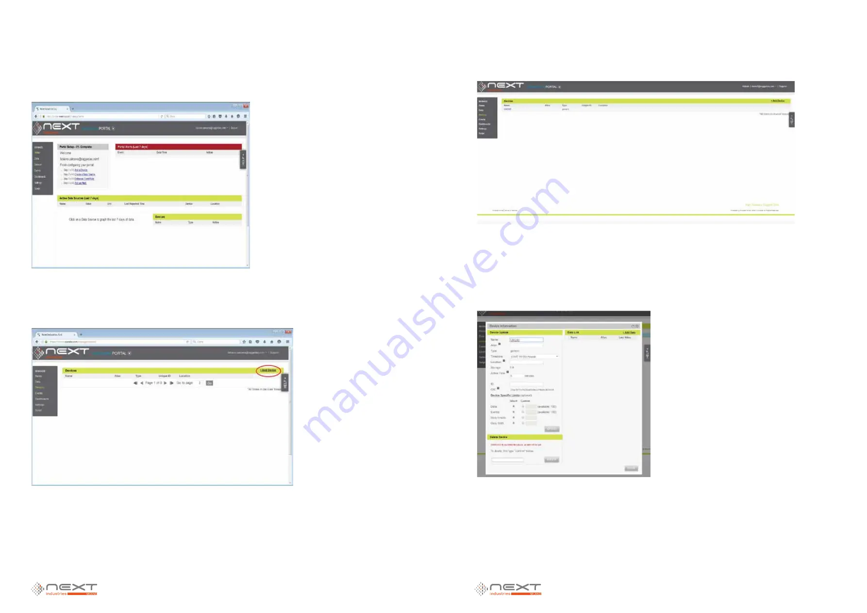
And access to your portal’s homepage:

The left menu on this page is to navigate through the portal sub sections.

In order to manage (and add) devices click on 

Device 

menu item and access to the fol-

lowing page:

In this page all devices currently added to the portal are showed. To add a new 

device, click on the link at the top right of the page and you will be guided through a 

step-by-step procedure to configure the device. At the end of procedure you should 

get the following  screen:

In this example a device called NI2400


has been added. You can always click  on the 

name of the device and review all the configurations done during the previous steps.

By clicking on the device name, you should get  the following page where you can see 

the CIK field:

this field has been automatically generated by the system and will permanently iden-

tify the device in the portal.

Figure 91

Figure 92

Figure 93

Figure 94

5

5

Содержание NI2400

Страница 1: ...NI2400 NI2400 DATALOGGER 24 CHANNEL ETHERNET DATA LOGGER with Embedded Web Server USER MANUAL Rev 02 del 03 08 2017 Redatto da R D Approvato da MKT...

Страница 2: ...product powering source must be divided from dangerous voltage parts with double insulation and must guarantee an insulation of at least 3000 Vrms Be sure to have in the plant a suitable protection fr...

Страница 3: ...y and Keyboard Functionality 29 Keyboard Overview 29 Display Overview 30 Firmware and Web Updates Vibrating Wire Firmware Update 32 Data Download 32 Datalogger Stop and Switch Off 35 Display Language...

Страница 4: ...nternal Web Server can be browsed to configure and download acquired data It can be used for Internet con nection Cloud FTP and EMAIL connections USB Host it allows the user to download measures event...

Страница 5: ...5 SmartModbus Sensors are powered from NI2400 a more powerful PSU should be used Warning ALL V OUT connections on the front panel in the upper terminal block expose the same V IN applied If you apply...

Страница 6: ...connected to channel 4 A and B terminals Wiring schemes are available from web server or in the APPENDIX of this manual Example 2 4 wires sensors User connects 3 sensors all of them are 4 wires First...

Страница 7: ...ENSOR1 will be connected to channel 1 A and B terminals channel 2 A and B terminals and channel 3 A and B terminals SENSOR2 will be connected to channel 4 A and B terminals channel 5 A and B terminals...

Страница 8: ...ted to channel 5 A and B terminals SENSOR4 will be connected to channel 6 A and B terminals Wiring schemes are available from web server or in APPENDIX of this manual Figure 11 Example 5 6 wires and 2...

Страница 9: ...be connected to channel 4 A and B terminals and channel 5 A and B terminals SENSOR3 will be connected to channel 6 A and B terminals and channel 7 A and B terminals Wiring schemes are available from w...

Страница 10: ...eter input frequency will be measured and logged in measure log Readable signal specifications Min 5V 2mA max Max 24V 10mA max Max Frequency 1KHz Accuracy 0 1Hz Inputs are optoisolated Example In orde...

Страница 11: ...same power source applied to NI2400 VIN Be careful to choose the right supply to power both datalogger and sensor GND same as V is the negative connection of power supply RS 485 allows daisy chain con...

Страница 12: ...er the proper con figuration of PC network card connect the PC to the NI2400 through an Ethernet crossover cable supplied Once connected through the supplied cable open any internet browser and put in...

Страница 13: ...4 Select Use this IP and write data you see in the picture below WEB CONNECTION AND OPENING Overview Here you will learn how to connect the NI2400 to the network and how to access the WEB Description...

Страница 14: ...he search bar select Advanced from left menu and then Connections 1 Flag DHCP Enable and then start NI2400 reboot 2 After Rebooting IP address has to be setted up look at chapter Computer IP settings...

Страница 15: ...rform some simple operations without using a computer connected to NI2400 NOTE Some operations data download on USB key FW update network card en abling etc can require the NI2400 to automatically res...

Страница 16: ...nu press Enter key Icons Date and Time IP address Powering Humidity on early models Temperature DL It shows NI2400 current status To return to main menu press ACQUISITION It is possible to see in real...

Страница 17: ...log alarms files in two ways PC through web interface USB through USB pen drive To download data through a PC connected to the NI2400 first configure the PC network card with the NI2400 s same class b...

Страница 18: ...s quantity the copy could take a few minutes During the copy will be displayed the following screen ATTENTION Do not disconnect the USB pen drive or cut off the NI2400 pow ering during the copy since...

Страница 19: ...the following screen Using Up and Down keys select System shutdown and press Enter You will see the following screen Now is possible to cut off the NI2400 power eg Extract the V IN clamp NOTE This swi...

Страница 20: ...onfiguration parameters channel configurations acquisition time etc delete and download logs Config mode is expected only for Admin user Stop NI2400 is stopped No acquisitions are in progress In this...

Страница 21: ...browser will keep the old language is necessary to completely delete internet browser cache Configuration of local analog channels In this manual is explained how to set up the local analog channels...

Страница 22: ...r requires six wires for example a ratiometric sensor Add 6 wires sensor For example if you push on button add 4 wires sensor in the underlying table a 4 wires sen sors is added and it is possible to...

Страница 23: ...se refer to manual Linear and Poly nomial Conversion Quick Start p olynomialcoe fficie nta b c d This field is enabled if the polynomial conversion has been se lected For further information please re...

Страница 24: ...ield editable from the user It indicates the numerical value to assign to the derived threshold The value has to be inserted taking into account the unit of measure of the reading vc alarm w ith logic...

Страница 25: ...ble to use them to connect a sensor after you saved the configuration select from left menu the entry channels configuration multiplexers the page multiplexers opens Here you could select mux 24ch thu...

Страница 26: ...ssary to check that their positions are the same If the positions changed it is necessary to re wire the sensors to the multiplexer MODBUS SENSORS What s Modbus Modbus is a serial communication protoc...

Страница 27: ...and a SmartModbus element Fig 3 SmartModbus is selected if the User has a generic modbus sensor Modbus Address is sensor s modbus address usually settable from the sensor Pre Measure Actions Some sen...

Страница 28: ...standby or reset Settings are quite similar to Pre Measure Ac tions Send Command which can be enabled or not and actions are Force Multiple Reg Write Coil Register Address is specified in Reg Address...

Страница 29: ...t if a sensor has more than 2 channels The NI2400 allows to create another sensor with the same Modbus address Fig 9 10 11 so user can select 4 or more creating other sensors registers to read data fr...

Страница 30: ...ay time between relay activation and acquisition process ADC Average Number Number of average computed by Analog to Digital Converter Simultaneous Relay Number number of simultaneously activated relay...

Страница 31: ...ter for more info WARNING BEWARE OF ENABLING THIS FIELD BEFORE ENABLING THIS FIELD BE SURE TO DELETE ALL MEASURE LOG PRESENT IN MEMORY IF MEMORY IS NOT CLEAR AT THE FIRST ACQUISITION THE DATALOGGER WI...

Страница 32: ...of events after which the datalogger will cease to trigger NEVER is the option to disable this feature and let the datalogger trigger EVERY set alarm After configuration click Save to proceed If you s...

Страница 33: ...ress Folder it allows to specify subfolder to be used The directory MUST exist Username and Password credentials used to connect to the server Port port used to connect to the server Tries number of a...

Страница 34: ...could be used with a seismic station and it is used to start one or more acquisitions extemporaneous NOTE in case of a rain gauge or anemometer no elaboration of reading is considered ex average spee...

Страница 35: ...e This field enables only for RAIN GAUGE and WIND GAUGE It indicates the unit of measure of the read value num b e r of re adings trigge r Editable field Numerical value This field enables only for TR...

Страница 36: ...he majority of Seismic Stations has the possibility in case of a seismic event to activated a digital output an output voltage If this signal is connected directly to the digi tal input IN1 of the NI2...

Страница 37: ...talogger and how to configure them 1 Why are Virtual Channels implemented in OM Family This paragraph shows benefits of Virtual Channels 2 Scripts Scripts are a fundamental section of Virtual Channels...

Страница 38: ...ts an analog channel prompts a dialog box to input channel number dig selects a digital channel prompts a dialog box to input channel number mux selects multiplexer position prompts two dialog boxes t...

Страница 39: ...config in the Virtual Channel row Figure 23 the user can edit Identification channel name and alarm properties Figure 69 Alarm configuration is the same for all channel types with High Low and Derivat...

Страница 40: ...TION Overview Advanced parameters are explained in this section Connection configuration for Ethernet and 3G modem parameters Measure log transfer for FTP server configuration Account management to ch...

Страница 41: ...sually provided by telephone opera tor WARNING Remember to set DNS also on RS 232 2G 3G modem Measure log data transfer This page contains data transfer settings Sending Measure block allows to choose...

Страница 42: ...uggedaq com DATALOGGER NI2400 NI2400 Account Management Here it is possible to change the passwords for User and Admin accounts and to change web language Date and Time In this screen it s possible to...

Страница 43: ...to generate Charts It s available on request and need to be activated with a Purchased Key Contact your dealer for more information It s possible to export data and save charts as pdf png or vector fi...

Страница 44: ...selection create up to 3 vertical axis related to that channel If different scales are presents this solves readability troubles Figure 83 Color window let the user select the color of that channels A...

Страница 45: ...ure 87 From this screen it s possible to print or download the chart Figure 88 You can now select the new chart from Saved charts selection and Plot every time you need It can be autoupdated after eve...

Страница 46: ...xers and virtual channels 16 registers will be exported Input A s last acquired measure Offset 0 1 input b Offset 2 3 sensor s tem perature Offset 4 5 Acquisition s timestamp Offset 6 7 8 9 10 11 12 1...

Страница 47: ...nput X Valid It indicates if matching Inputs are valid or not If sensor is configured as Volt 1CH registers status will be Input A Valid 1 Input B Valid 0 Input temp Valid 0 For a digital single chann...

Страница 48: ...X 2 BASE_MUX 3 MSB LSB Input B MUX 1 CH1 MUX1 CH1 BASE_MUX 4 BASE_MUX 5 MSB LSB Temperature MUX 1 CH1 MUX1 CH1 BASE_MUX 6 BASE_MUX 14 Timestamp acquisition MUX 1 CH1 MUX1 CH1 BASE_MUX 15 Flags MUX 1 C...

Страница 49: ...n2 DigIn2 BASE_DIN 20 BASE_DIN 21 MSB LSB Temperature DigIn2 DigIn2 BASE_DIN 22 BASE_DIN 30 Timestamp acquisition DigIn2 DigIn2 BASE_DIN 31 Flags DigIn2 DigIn2 BASE_VIRT 0 BASE_VIRT 1 MSB LSB Input A...

Страница 50: ...el 1 16 BASE_MUX Address 1 16 Channel 1 24 Digital Inputs 8 CH 24 CH BASE_DIN 12416 12672 Channel_ADDRESS Channel 1 16 BASE_DIN Channel 1 2 Virtual Channels 8 CH 24 CH BASE_VIRT 12448 12704 Channel_AD...

Страница 51: ...7 16408 Device name 8 16409 External digital input status LSB External digital output status MSB Datalogger Status This register contains datalogger status REGISTER VALUE DESCRIPTION 1 Ready 2 Run 3 S...

Страница 52: ...ple of Device name register s chaining Device name Bridge_1 Device name 1 MSB Device name 1 LSB Device name 2 MSB Device name 2 LSB Device name 3 MSB Device name 3 LSB Device name 4 MSB Device name 4...

Страница 53: ...e link at the top right of the page and you will be guided through a step by step procedure to configure the device At the end of procedure you should get the following screen In this example a device...

Страница 54: ...on Navigate to the page Advanced Connections In this page you should configure all parameters that allow the datalogger to access the Internet These settings depend on your network configuration Acqui...

Страница 55: ...red on the physical device in the first paragraph in this chapter In this example the data source will be added AN_1_A AN_1_B and AN_2_A By clicking on Add Data you get the followingpage WARNING Only...

Страница 56: ...e dashboard thumbnail you finally have access to the dashboard Here you can add widgets needed to monitor the data sources by clicking on ADD WIDGET button By clicking on this button you can select a...

Страница 57: ...ata points at the same time line and column chart no sense for graph that shows only last value like gauge and image overlay Refresh rate the refreshing period of the graph In this example a line char...

Страница 58: ...NFIG clamp 3 control that the power supply system works is correctly sized and respects the character istic declared on datasheet 4 make sure you hadn t set the NI2400 in Timed mode using the webpage...

Страница 59: ...lamp for 10 seconds and try to reconnect 2 reboot the PC and try to connect 3 make sure you configured appropriately the network card of the PC that is it is part of the same subnet mask of the NI2400...

Страница 60: ...twork SECONDLY INSURE WITH YOUR ESP THAT 1 there are no momentary breakdowns on ESP server 2 the username and password of your e mail account are valid and accepted 3 that the e mail account you want...

Страница 61: ...SEND ANY DATA ON FTP SERVER ALSO IF CONFIGURED Follow this step testing after each 1 verify the events log and refer to manual Codes Alarms Events to understand the pos sible logs 2 if you use a HSPA...

Страница 62: ...instruments on the NI2400 screw clamps 4 verify that the configured parameters are coherent and correct according to the type of connected instrument power supply warm up time etc 5 consult the refere...

Страница 63: ...24 www ruggedaq com DATALOGGER NI2400 NI2400 0125 www ruggedaq com DATALOGGER NI2400 NI2400 Thermistor Thermocouple Figure 119 Figure 120 Vibrating Wire Voltage External Supply Figure 121 Figure 122 7...

Страница 64: ...0127 www ruggedaq com DATALOGGER NI2400 NI2400 4 WIRES SENSORS 4 20 Transmitter 4 20 Transmitter 2 channel External Supply Figure 123 Current Loop 2 Channels Internal and External Supply Potenziomete...

Страница 65: ...TALOGGER NI2400 NI2400 0129 www ruggedaq com DATALOGGER NI2400 NI2400 Potenziometer 2 Channel PT100 PT200 PT500 PT1000 Figure 127 Figure 128 Ratiometric External Supply Servo BiAxial External Supply F...

Страница 66: ...NI2400 NI2400 0131 www ruggedaq com DATALOGGER NI2400 NI2400 Vibrating Wire with Thermistor NTC Voltage Figure 131 Figure 132 Voltage 2 channels External supply 6 WIRES SENSORS 2 40mA Transmitter 2 ch...

Страница 67: ...uggedaq com DATALOGGER NI2400 NI2400 0133 www ruggedaq com DATALOGGER NI2400 NI2400 Ratiometric Servo Biaxial Figure 136 Figure 135 Figure 136 Servo UniAxial 5 Wires Voltage 2 channel Figure 137 Figur...

Страница 68: ...e ruggedaq com 8 Webserver on board 24 Differential Analog Input Channels Measures Thermocouples PT100 RTD NTC Thermistor mV mA mV V View Data in real Time or Store to 2 GB Internal Memory GPRS Modem...

Страница 69: ...ock It shows relative position so if you start connecting sensors from the first you will not have to leave unused positions except for the ground connection of every block if not used Multiplexers ar...

Страница 70: ...FS for Pt100 and NTC with Standard Measure ment 0 13 mV mA FS with Max Speed Measurement Temperature Drift 10 ppm C range 30 to 70 C Input Noise Voltage 5 42 V pp Input Limits 12V DC Common Mode Rejec...

Страница 71: ...OUT Switched on and off under program control V OUT is the unregulated input power supply V IN 1 A Power supply management Always on or energy safe RS485 2 Opto Isolated Connection 5 screw clamp port...

Страница 72: ...xternal Power Supply Sleep Mode MAX 315 A ON 62 mA ON with ethernet connected 87 mA ON with display ON 115 mA ON with display ON and ethernet connected 142 mA Analog Initialization 115 mA Measurement...

Страница 73: ...Next Industries S r L Via G Di Vittorio 2 F 20065 Inzago MI Italy T 39 02 95764356 info ruggedaq com www ruggedaq com NI2400 DATALOGGER INTERNET OF THINGS SENSORS WEB SOFTWARE DATALOGGERS...

Отзывы: