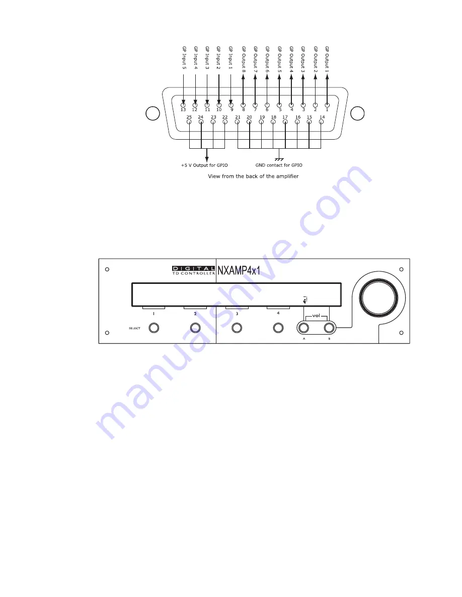
MENU DESCRIPTION
This menu allows choosing the way the GPIO are handled by the NXAMP Powered
TDcontroller. There are currently 5 modes of GPIO which are described bellow.
To change the current GPIO mode, press Edit (
‘Select 4’
button) and turn the wheel up or
down to the selected GPIO mode. Once done, press OK (
‘Select 4’
button) to validate your
choice.
GPIO is set to MODE 0 GPIO
Edit
To put a GPI pin in the ‘High’ state, connect it to one of the ‘+5 Volts’ output on the GPIO
DB-25 connector. See above in the user manual for proper pin-out. When nothing is
connected to a GPI, the state is ‘Low’ (internal pull-down). A switch can be directly
connected to this input, but if a GPIO output of another device should be connected, it is
mandatory to ensure a galvanic insulation between the two devices. Only direct connection
is authorized between NXAMP when they are located in the same rack.
GPIO mode 0 (Default mode / DMU mode)
In this default mode the GPIO port can be used with a NEXO DMU unit. See further in this
manual for more details about DMU set up.
GPIO mode 1 (Basic remote control mode)
This mode is intended to be used with permanently ‘High’ or ‘Low’ state signals. There is an
action depending on the state of each GPI. A state is validated when the state of the pin
has changed and is stable for 1 second. Here is the detail:
PAGE 63 OF 140
Содержание NXAMP4X1
Страница 2: ......
Страница 110: ...DMU DIGITAL METERS UNIT FOR NXAMP PAGE 110 OF 140 ...
Страница 118: ...DPU DIGITAL PATCHING UNIT FOR NXAMP SPK8 To STM Stack SPK4 Link between DPUs PAGE 118 OF 140 ...
Страница 125: ...NXWIN4 SOFTWARE FOR NXAMP FIRMWARE UPGRADE PAGE 125 OF 140 ...
Страница 139: ...ROHS CERTIFICATE ROHS certificate PAGE 139 OF 140 ...


