Copyright © NetPing east Co., Ltd E-mail:
Phone:+886-2-23121582
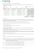
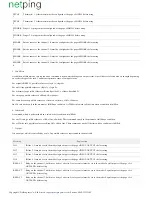
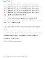
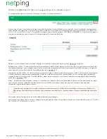
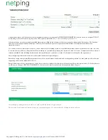
TSTAT
1
Thermostat 1. A thermostat must be configured at the page
«LOGIC» before using
TSTAT
2
Thermostat 2. A thermostat must be configured at the page «LOGIC» before using
PINGER
1
Pinger 1. A pinger must be configured at the page «LOGIC» before using
PINGER
2
Pinger 2. A pinger must be configured at the page «LOGIC» before using
SMOKE
1
Smoke sensor at the channel 1. It must be configured at the page
before using
«SMOKE»
SMOKE
2
2.
Smoke sensor at the channel
It must be configured at the page «SMOKE» before using
SMOKE
3
3.
Smoke sensor at the channel
It must be configured at the page «SMOKE» before using
SMOKE
4
4.
Smoke sensor at the channel
It must be configured at the page «SMOKE» before using
5. Condition
A condition, within which a rule is used and a command is issued, which changes an output status. An available set of conditions is changed depending
on a selected type of the task. Conditions represent a sense of an input status.
For a signal «RESET», possible values are «
logic 1», «logic 0».
For an IO line possible values are «
», «
».
logic 1
logic 0
For a thermostat, possible values are «
», «
».
Below Specified Т
Above Specified Т
For a pinger, possible values are «Silent», «Responds».
For a smoke sensor, possible values are «
», «
»,
Normal
Alarm
«Off», «Failure».
An « » rule works only in the moment of fulfilling a condition. A «
» rule works all the time when a condition is fulfilled.
If
While
6. Command
A command, which is performed when a rule works (a condition is fulfilled).
For an « » rule, possible values are «
», «
»,
. These commands work in the moment of fulfilling a condition.
If
Off
On
«Switch»
For a «
» rule, possible values are «
», «
». These commands work all the time while a condition is fulfilled.
While
Keep Off
Keep On
7. Output
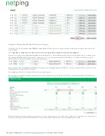
It is an output, which is controlled by a rule. Its possible values are represented in the next table:
Marking
Explanation
IO 1
IO line 1. It must be set to the mode
before using
«logic output» at the page «INPUT-OUTPUT»
IO 2
IO
2.
line
It must be set to the mode «logic output» at the page «
»
INPUT-OUTPUT before using
IO 3
IO
3.
line
It must be set to the mode «logic output» at the page «
»
INPUT-OUTPUT before using
IO 4
IO
4.
line
It must be set to the mode «logic output» at the page «
»
INPUT-OUTPUT before using
RELAY 1
Relay on the channel 1, built into a body of a device. A relay control must be set to the mode «
» at the page «
Logic Output
AC
» before using
OUTLETS
RELAY 2
2,
.
Relay on the channel
built into a body of a device A relay control must be set to the mode «Logic Output» at the page «AC
OUTLETS» before using
RELAY 3
3,
.
Relay on the channel
built into a body of a device A relay control must be set to the mode «Logic Output» at the page «AC
OUTLETS» before using


