12
relative spacing, in order to achieve the effect of the actual placing.
Operation introduction
(1) Single PCB: Only need to enter “1” in the row and column, some other useless function will
turn grey. The “left bottom” is functional, which means the first PCB.Then you can press “align”
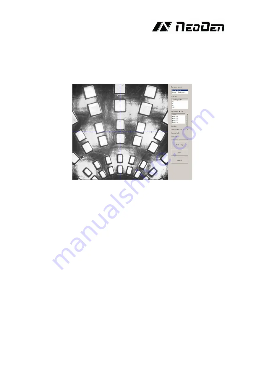
to go to the screen of vision and get the coordinate of first component, see image 2-2.
After saving the coordinate, the screen will automatically turn back to “PCB information” . Click
“Create panelized list” to get the information of “Panel 1”. Now we’ve finished setting of first
component of PCB.
(2) Panelized PCB: the sequence is same to single PCB, but please pay some attention to several
points below.
The row and column is determined by the positioning of PCB on working area. The
direction along the rails is the column. Enter data in the row and column.
About the data collection of “left bottom” , “left top” and “right top”, we should take the
“left bottom” as the basic, and then go to set “left top” and “right top”. Once all the data is
collected, the machine can calculate and process the information of panelized PCB. Please
refer to the data collecting method of each position information as following:
The data of “left bottom” is collected according to first component in programming file.
Press “align” find the left bottom panel which is nearest to the feeding position, after saving
the data, it will return to the “PCB information” automatically.
The data of “left top” is collected according to component (its position is same to that on “left
bottom”). Press “align” find the left top panel which is furthest to the feeding position, after
saving the data, it will return to the “PCB information” automatically.
The data of “right top” is collected according to component (its position is same to that on
“left bottom”). Press “align” find the right top panel which is furthest to the feeding position,
after saving the data, it will return to the “PCB information” automatically.
Fig.2-2


