background image

UNIVERGE SV8100

Issue 4.1

System Hardware Manual

6 - 7

6.

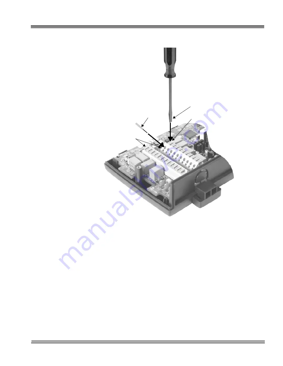
Repeat Steps 4 and 5 for any additional connections required.

7.

Replace the cover and tighten the screw to hold the cover in place.

8.

If required for the function being used, insert the RCA connectors into 
the CN2 (Channel 1) and CN3 (Channel 2) connectors on the back of the 
PGD(2)-U10 ADP.

Figure 6-6  Connecting Cable to the PGD(2)-U10 ADP

Flat-head screwdriver

Press down

Cable

CN4, CN5

Содержание Univerge SV8100

Страница 1: ...System Hardware Manual Issue 4 1 February 2011...

Страница 2: ...THIS PAGE INTENTIONALLY LEFT BLANK...

Страница 3: ...stem Specifications Section 1 General Information 2 1 Section 2 System Block Diagram 2 1 Section 3 Maximum System Capacities 2 5 3 1 System Configuration SV8100 2 6 Section 4 Power Based Calculator Ch...

Страница 4: ...ignaling 2 24 5 6 3 External Equipment Connection 2 25 5 6 4 Music Source for Music on Hold via Chassis 2 25 5 6 5 Music Source for Station Background Music via ACI 2 25 5 6 6 External Paging Audio 2...

Страница 5: ...the 9 5 Chassis 3 36 2 7 Installing the 19 Chassis 3 39 2 7 1 Unpacking the Equipment 3 40 2 7 2 Before Installation 3 40 2 7 3 Installing the 19 Controlling Chassis 3 41 2 7 4 Installing Expansion B...

Страница 6: ...ery Installation 3 64 3 2 3 CHS LARGE BATT BOX to CHS2U Connection 3 68 3 3 Installing the External Batteries 9 5 Chassis 3 72 3 3 1 Battery Installation 3 72 3 3 2 CHSGW SMALL BATT BOX to CHS2U GW Co...

Страница 7: ...h Software 4 8 2 5 Blade Capacities 4 9 2 6 Powering Up the SV8100 4 9 2 6 1 Performing a Cold Start 4 9 2 6 2 Performing a Hot Start 4 10 2 6 3 Resetting the System 4 10 2 6 3 1 Initial Programming 4...

Страница 8: ...tallation 4 36 3 4 3 Switch Settings 4 36 3 4 4 LED Indications 4 37 3 4 5 Connectors 4 38 3 5 PZ 32IPLB PZ 64IPLB PZ 128IPLB Voice over IP Daughter Boards Available June 2011 4 39 3 5 1 Description 4...

Страница 9: ...55 4 3 4 Connectors 4 57 4 4 PZ 4LCA PZ 8LCE 4 Port 8 Port SLI Daughter Boards 4 58 4 4 1 Description 4 60 4 4 2 Installation 4 61 4 4 3 Connectors 4 62 4 5 CD LTA Dterm SLT Combination 4 63 4 5 1 Des...

Страница 10: ...81 5 4 3 Connectors 4 82 5 4 4 Termination Switch Settings 4 83 5 5 CD 4DIOPB DID OPX Interface 4 84 5 5 1 Description 4 84 5 5 2 Installation 4 85 5 5 3 LED Indications 4 85 5 5 4 Connectors 4 86 5...

Страница 11: ...ion 4 105 6 2 3 LED Indications 4 105 6 3 CD ETIA Gigabit PoE Switch 4 106 6 3 1 Description 4 106 6 3 2 Installation 4 107 6 3 2 1 Stacking Architecture 4 107 6 3 2 2 CD CP00IP Address Assignment 4 1...

Страница 12: ...3 1 5 ITL 12PA 1 BK TEL 5 18 3 1 6 ITL 24D 1 BK TEL ITL 24D 1 WH TEL 5 19 3 1 7 ITL 32D 1 BK TEL ITL 32D 1 WH TEL 5 20 3 1 8 ITL 320C 1 BK TEL 5 21 Section 4 Install Multiline Terminals 5 23 4 1 Conne...

Страница 13: ...minal 5 44 4 10 1 Wall Mounting a Multiline Terminal using the Base Plate 5 44 4 10 1 1 Adjusting the Hanger Hook 5 44 4 10 1 2 Wall Mounting the Multiline Terminal 5 45 4 10 1 3 Removing the Multilin...

Страница 14: ...l Mounting 5 73 Section 7 Bluetooth Cordless Handset 5 74 7 1 Bluetooth Cordless Handset BCH Interface 5 74 7 2 Selecting a Location 5 75 7 3 Controls and Indicators 5 76 7 4 Installing the Bluetooth...

Страница 15: ...5 93 9 2 Wall Mounting the SLT Adapter 5 94 Chapter 6 Installing SV8100 Optional Equipment Section 1 General Information 6 1 Section 2 PGD 2 U10 ADP 6 1 2 1 Using a PGD 2 U10 ADP 6 1 2 2 LED Indicatio...

Страница 16: ...External Music on Hold 6 24 Section 9 Night Mode Selection 6 27 9 1 Night Mode Selector Switch 6 27 9 2 Connecting a Night Mode Selector Switch 6 27 Section 10 Telephone Labeling 6 27 10 1 DESI Printe...

Страница 17: ...e 6 38 11 4 APR L UNIT 6 38 11 4 1 APR L UNIT Switch Settings 6 39 11 4 2 Installing the APR L UNIT 6 40 11 5 PSA L BK UNIT PSA L WH UNIT 6 43 11 5 1 Installing the PSA L Adapter 6 44 11 5 2 Using the...

Страница 18: ...1 UNIVERGE SV8100 ___________________________________________________________________________________ xvi Table of Contents ____________________________________________________________________________...

Страница 19: ...OR BATTERY DISPOSAL DO NOT PLACE USED BATTERIES IN YOUR REGULAR WASTE THE PRODUCT YOU PURCHASED CONTAINS LITHIUM NICKEL CADMIUM OR SEALED LEAD BATTERIES LITHIUM NICKEL CADMIUM OR SEALED LEAD BATTERIES...

Страница 20: ...y sold or a local seller of automotive batteries Contact your local waste management officials for other information regarding the environmentally sound collection recycling and disposal of the batter...

Страница 21: ...try or network specific features should match the supported features of the system For an overview of the supported features refer to the detailed documentation that comes with this system contact you...

Страница 22: ...t a fine may be imposed for illegal disposal of electrical and electronic products via the general municipal waste stream In order to facilitate separate disposal and environmentally sound recycling a...

Страница 23: ...Division Multiplexing TDM based infrastructure such as analog telephones digital telephones DT300 series analog networks and digital networks T1 E1 ISDN etc The new compact 19 chassis provides 104 tot...

Страница 24: ...ions between legacy stations trunks Connection between IP network and legacy network is made via VoIP daughter board on the CPU blade which converts packet based voice data to TDM based voice data and...

Страница 25: ...the main blade is mounted only in an initial supply line trunk interfaces can be easily expanded by adding the daughter blade The maximum number of ports for the line trunk blades is 8 16 ports with...

Страница 26: ...Joint Bracket for 6 slot Chassis SV8100 CHS2U RACK MOUNT KIT Rack Mount for CHS2U Chassis SV8100 CHS1U 2U WALL MOUNT KIT Wall Mount Set for CHS2U Chassis SV8100 CHS Stand Kit K Stand Mount Kit for 2U...

Страница 27: ...port Digital Station Interface SV8100 CD 4COTA COT 4 port Loop Start Trunks SV8100 PZ 4COTE COTDB 4 port Loop Start Trunks on CD 4COTA SV8100 CD 4LCA LC 4 port Single Line Telephone Interface SV8100 P...

Страница 28: ...xternal Battery 6 slot Chassis SV8100 Table 1 6 Digital Multiline Terminal DT300 Series Equipment List Equipment Name Equipment Description Product Code DTL 2E 1 BK TEL Economy Digital 2 button Teleph...

Страница 29: ...ITL 24D 1 BK TEL ITL 24D 1 WH TEL Value IP 24 button Display Telephone SV8100 ITL 32D 1 BK TEL ITL 32D 1 WH TEL Value IP 32 button Display Telephone SV8100 ITL 12PA 1 BK TEL Value IP 12 button Teleph...

Страница 30: ...r Side Panel Left and Right Label each Sheet SV8100 DESI ITL DTL SIDE LCDV 25 PKG DESI Sheet for Value Telephone LCD Clear Side SV8100 DESI ITL DTL SIDE LCDS 25 PKG DESI Sheet for Sophisticated Teleph...

Страница 31: ...BK SV8100 LKPANEL 6BTN L BK UNIT Spare Plastic Cover Kit 6 button BK SV8100 LKPANEL 12BTN L BK UNIT LKPANEL 12BTN L WH UNIT Spare Plastic Cover Kit 12 button SV8100 LKPANEL 24BTN L BK UNIT LKPANEL 24...

Страница 32: ...Value Telephone SV8100 KeyKitPanel Retro BK Unit KeyKitPanel Retro WH Unit Spare Plastic Cover Key Kit for Retro Telephone SV8100 KeyKitPanel Sophi BK Unit KeyKitPanel Sophi WH Unit Spare Plastic Cov...

Страница 33: ...Green Metallic 1 set consists 10 of panels SV8100 LKPANEL 24BTN L Orange M UNIT Color LK panel 24button for Value Orange Metallic 1 set consists 10 of panels SV8100 LKPANEL 24BTN L D Brown M UNIT Colo...

Страница 34: ...00 BS F L BK KIT BS F L WH KIT French Keypad SV8100 BS S L BK KIT BS S L WH KIT Spanish Keypad SV8100 ITL GigADP 1 Gigabit Adapter SV8100 BS ACD L BK KIT BS ACD L WH KIT ACD Support Keypad SV8100 BS I...

Страница 35: ...Handset BK Push to Mute Handset SV8100 ITL DTL PTT Handset BK Push to Talk Handset SV8100 GBA L UNIT Gigabit Adapter SV8100 AC L UNIT AC Adapter for GBA L UNIT SV8100 BS V HOTEL L BK UNIT Standard Ho...

Страница 36: ...Issue 4 1 UNIVERGE SV8100 1 14 Introduction to SV8100...

Страница 37: ...n the Blade is installed Table 2 1 List of Abbreviations lists abbreviations used in the diagram Table 2 1 List of Abbreviations Abbreviation Description ACD Automatic Call Distribution ADA Analog Rec...

Страница 38: ...t on CPU FT1 Fractional T1 GSWU Power over Ethernet Gigabit Switch IDF Intermediate Distribution Frame IPT IP Trunk P2P CCIS on CPU ISDN Integrated Service Digital Network LAN Local Area Network LC Si...

Страница 39: ...uter Blade SERIAL Serial Port on CPU SLT Single Line Telephone SMDR Station Message Detail Recording TDSW Time Division Switch on CPU USB Universal Serial Bus on CPU VM00 UMS Blade Server Blade SV8100...

Страница 40: ...Issue 4 1 UNIVERGE SV8100 2 4 SV8100 System Specifications Figure 2 1 SV8100 System Block Diagram...

Страница 41: ...um of three additional chassis onto the controlling chassis This provides a maximum of 24 slots and 368 digital terminals To obtain a the maximum port capacity of 512 ports two systems can be linked t...

Страница 42: ...ection and use of additional 19 chassis the system can be expanded to a maximum of 512 ports The 19 chassis consists of a controlling chassis chassis with CPU blade and the ability to expand the syste...

Страница 43: ...re Manual 2 7 Figure 2 3 19 Controlling and Expansion Chassis 6 Slots 18 Slots IP Connection 24 Slots The 9 5 chassis graphics shown in the horizontal position are for illustration purposes only Actua...

Страница 44: ...Chassis x4 Comments Number of Slot s for Interface Package 5 Slots 6 Slots 23 Slots Chassis CHS2U 19 Chassis 1 3 4 Virtual slot in NetLink is limited to maximum of 240 Expansion PZ BS10 3 jack Expans...

Страница 45: ...r of Slot s for Interface Package 3 Slots 5 Slots 6 Slots 23 Slots Common Control Blades CD CP00 1 1 0 0 PZ 32IPLA 32 port VoIP Daughter Board 1 1 0 1 This unit provides 32 VOIP Gateway channels PZ 64...

Страница 46: ...16DLCA 16 Digital Station Interface 2 5 6 23 CD LTA 8 Digital 2 Single Line 2 5 6 23 A maximum of 1 can be installed without ME50 card fitted An optional PZ 4COTE or PZ 2BRIA can be installed Trunk B...

Страница 47: ...Switching Hub with Power over Ethernet 2 3 3 12 CD CCTA CCIS Trunk Interface Common Channel Handler 2 4 4 4 CD RTB Router 2 1 2 1 R2 CD VM00 Voice Mail and Server 1 1 1 1 Maximum of One per system PZ...

Страница 48: ...the CD LTA can have a PZ 2BRIA or the PZ 4COTE daughter board mounted Table 2 5 Daughter Board Combinations Daughter Board PZ 2BRIA PZ 4COTE PZ 4LCA PZ 8LCE PZ 8DLCB Controlling Chassis CD LTA 8 Digi...

Страница 49: ...um Number of Package Installed Refer to Table 2 8 Terminal Power Factor below for the Terminal Adapter power chart Table 2 6 Board Power Factor Board Power Factor Total 7 Item Power Factor CD CP00 1 C...

Страница 50: ...TL 320C 1 TEL 6 ITL 24D 1 TEL 4 ITL 2E 1 TEL 4 ITL 6DE 1 TEL 4 SLT Standard 28V 0 8 Long Line 48V 2 PGD 2 U10 ADP 2 SLT Adapter 5 ITL factors are calculated using the CD ETIA blade Table 2 9 IP Termin...

Страница 51: ...122mA 2 9W 68mA 3 3W 122mA 2 9W Label Indication IP Value Sophisticated Maximum watts when adding options or modular upgrades IP Value Maximum watts when ITL 12D 1 TEL is changed to ITL 8LD 1 TEL or I...

Страница 52: ...es Loop Resistance and Cable Length Table 2 14 Dterm Series i or Dterm IP Terminal Loop Resistance and Cable Length Table 2 15 Cable Connection Between the Analog Port and the Single Line Equipment Ta...

Страница 53: ...100m ITL 8LD 1 BK TEL ITL 8LD 1 WH TEL Cat 5 Cat 6 Ethernet 328 1 ft 100m ITL 12BT 1 BK TEL Cat 5 Cat 6 Ethernet 328 1 ft 100m ITL 12D 1 BK TEL ITL 12D 1 WH TEL Cat 5 Cat 6 Ethernet 328 1 ft 100m ITL...

Страница 54: ...00 107 2000 2000 DTH 16 1 TEL DTR 16 1 TEL 35 660 1320 107 2000 2000 DTH 16D 1 TEL DTR 16D 1 TEL 35 660 1320 107 2000 2000 DTH 32D 1 TEL DTR 32D 1 TEL 26 500 1000 107 2000 2000 DTH 16LD 1 TEL 37 700 1...

Страница 55: ...ncy 47Hz 63Hz Rated frequency 50 60Hz Phase and Wire Single Phase 2 Line PE Type Grounding Requirements No 14 AWG copper wire Feeding Voltage Dterm OPX DID 48V SLT 25mA 28V With input voltage of 230 V...

Страница 56: ...Console ADA APR Operating Temperature 0 C 40 C Recommended Long Term Temperature 20 C 60 C Operating Humidity 10 90 RH non condensing Recommended Long Term Humidity 10 90 RH Blades PZ BS10 PZ BS11 PZ...

Страница 57: ...rature 40o C 75o C Operating Humidity 20 95 RH non condensing Recommended Long Term Humidity 10 95 RH 5 4 Outside Line Types The following outside lines can be used with the UNIVERGE SV8100 system 4 w...

Страница 58: ...ng PCM A Law TDM Clock 2 048 MHz TDM Data Bus 8 bit TDM Timeframe 125 s 5 5 3 Control This section indicates the speed or capacity Control Stored program with distributed processing Central Processor...

Страница 59: ...rent 250 mA Single Line Telephone Standard 2500 Set 500 type network Nominal Current 25 mA Ring Signal 56 Vac RMS 20 Hz SLTII 1 U ADP Standard 2500 Set 500 type network Nominal Current 30 mA Ring Sign...

Страница 60: ...stem Pulse Rate 10 0 5 pps 20 1 0 pps Percent Break 60 1 5 Interdigit Interval 0 pps 20 pps 770 ms 830 ms 5 6 2 Dual Tone Multifrequency DTMF Address Signaling DTMF signaling includes push button or T...

Страница 61: ...U10 ADP Door Lock Release or General Purpose Relay via PGD 2 U10 ADP Printer for SMDR by LAN PC by LAN 5 6 4 Music Source for Music on Hold via Chassis Auxiliary Input 0 6V PPS Signal Level Input Imp...

Страница 62: ...backup 5 7 1 System Backup Optional During a power failure the system can be backed up using the CHS2U BATT MTG KIT for a backup time of 10 minutes or one of the CHS LARGE BATT SETs for a backup time...

Страница 63: ...z 0 01 kg 0 12 in 3 mm 2 56 in 65 mm 1 22 in 31 mm CD LTA 6 70 oz 0 19 kg 0 98 in 25 mm 5 71 in 145 mm 7 09 in 180 mm MGN U10 ETU 14 6 oz 0 41 kg 1 89 in 48mm 11 47 in 290 mm 8 46 in 214 mm CHS LARGE...

Страница 64: ...5 kg 0 60 in 15 mm 9 45 in 240 mm 5 12 in 130 mm CD 2BRIA 5 99 oz 0 17 kg 0 98 in 25 mm 9 45 in 240 mm 7 68 in 195 mm PZ 2BRIA 4 02 oz 0 114 kg 0 60 in 15 mm 4 72 in 120 mm 7 68 in 195 mm CD PRTA 5 5...

Страница 65: ...n 75 mm 4 45 in 113 mm 4 13 in 105 mm Digital Multiline Terminal DTL 2E 1 BK TEL 35 27 oz 1 0 kg 4 41 in 112 mm 7 05 in 179 mm 8 86 in 225 mm DTL 6DE 1 BK TEL 38 8 oz 1 1 kg 4 41 in 112 mm 7 05 in 179...

Страница 66: ...4 41 in 112 mm 8 94 in 227 mm 9 84 in 250 mm Optional 8LK L BK UNIT 8LK L WH UNIT 7 05 oz 0 2 kg 1 77 in 45 mm 1 15 in 29 3 mm 8 82 in 224 mm ADA L UNIT 2 82 oz 0 08 kg 98 in 25 mm 2 56 in 65 mm 3 23...

Страница 67: ...4 92 in 125 mm 60 DSS WM L UNIT 1 41 oz 0 04 kg 0 99 in 25 3 mm 3 4 in 86 5 mm 4 92 in 125 mm G955 Wireless Handset 3 13 oz 0 08 kg 4 96 in 126 mm 1 77 in 45 mm 0 78 in 20 mm MH240 3 53 ox 0 1001 kg...

Страница 68: ...Issue 4 1 UNIVERGE SV8100 2 32 SV8100 System Specifications...

Страница 69: ...face etc In skin Application Blades In skin UMS In Skin Router etc It also houses the BUS Interface Blade Power Supply Unit PSU and Cooling FAN When the CD CP00 blade is installed in the first 19 chas...

Страница 70: ...Slot for Legacy Line Trunk blades and Application blades six slots When used as controlling chassis the CD CP00 is mounted in Slot 1 shown Slot for PZ BS10 PZ BS11 blade Connection with CHS2U chassis...

Страница 71: ...ots for station trunk and optional blades The chassis can be wall mounted or stand mounted The first part of the this chapter describes the differing types of mounting options and the rest of this sec...

Страница 72: ...power supply etc The chassis is secured to the wall with a wall mount bracket Ensure that enough space is available to allow the installation of additional expansion chassis 2 1 1 CHS2U Chassis Wall...

Страница 73: ...UNIVERGE SV8100 Issue 4 1 System Hardware Manual 3 5 2 Mark and drill the six holes required for a wall installation 3 Align screw holes in wall mount brackets with drilled holes...

Страница 74: ...e wall Refer to Figure 3 6 Install Wall Mount Brackets with Screws for screw location 5 Using four screws secure the metal fittings on the Left and Right sides of the 19 chassis Refer to Figure 3 7 In...

Страница 75: ...UNIVERGE SV8100 Issue 4 1 System Hardware Manual 3 7 Figure 3 7 Install Wall Mount Brackets with Screws...

Страница 76: ...etal fitting and upper wall mount bracket with a single screw see Figure 3 8 Secure Metal Fitting to Upper Wall Mount Bracket with a Screw 7 Using two screws secure the metal fitting to the lower wall...

Страница 77: ...Attach the supplied cable support bracket to either end of the lower wall mount bracket with a single screw refer to Figure 3 10 Attach Cable Support Bracket with Screw on page 3 10 Figure 3 9 Secure...

Страница 78: ...ling the SV8100 Chassis 9 The cable support bracket can be installed any of the four corners of the 19 chassis refer to Figure 3 11 Attach Cable Support Bracket with Screw on page 3 11 Figure 3 10 Att...

Страница 79: ...ssis Grounding on page 3 52 for complete details on grounding the system 11 Refer to 2 7 Installing the 19 Chassis on page 3 39 to continue installation of the chassis or Chapter 5 paragraph 2 2 Insta...

Страница 80: ...hassis Installation 1 Use the template shown in Figure 3 12 Floor Mount Spacing Guide for required spacing before drilling holes for 0 39 10mm anchor bolts locally procured 2 Mark and drill the four h...

Страница 81: ...bber feet to the bottom of the chassis 5 Position the chassis on top of the CHS BASE UNIT 6 Secure the chassis to the CHS BASE UNIT using eight screws supplied with the CHS2U JOINT BRACKET KIT Figure...

Страница 82: ...Refer to 2 7 Installing the 19 Chassis on page 3 39 to continue installation of the chassis or Chapter 5 paragraph 2 2 Installing an Extension or Trunk Blade on page 4 4 for installation of blades 2...

Страница 83: ...m of each chassis 2 Using supplied screws in the CHS2U JOINT BRACKET KIT attach metal brackets to both ends of the 19 chassis and the CHS BASE UNIT Refer to Figure 3 17 Install Metal Brackets with Scr...

Страница 84: ...tallation of blades 2 3 Stand Mounting the 19 Chassis A single or multiple chassis can be stand mounted Controlling and Expansion chassis can be stand mounted using the CHS2U STAND KIT K and CHS2U STA...

Страница 85: ...dware Manual 3 17 3 Using supplied screws secure the CHS2U STAND KIT to the floor refer to Figure 3 20 Secure Stand Mount to Floor with Screws on page 3 18 Figure 3 19 Secure CHS2U Chassis to CHS2U ST...

Страница 86: ...Chassis Grounding on page 3 52 for complete details on grounding the system 5 Refer to 2 7 Installing the 19 Chassis on page 3 39 to continue installation of the chassis or Chapter 5 paragraph 2 2 In...

Страница 87: ...to the CHS2U STAND KIT and will require an additional CHS2U STAND KIT EXT per chassis 1 Install the five rubber feet to the bottom of each chassis 2 Each additional chassis will require CHS2U STAND K...

Страница 88: ...sis 3 Metal brackets from the CHS2U JOINT BRACKET KITs will be required to secure the top end of the chassis with screws See Figure 3 23 Install Additional CHS2U STAND KIT EXT on page 3 21 Figure 3 22...

Страница 89: ...t the ground wire to all chassis Refer to 2 7 5 Install 19 Chassis Grounding on page 3 52 for complete details on grounding the system 6 Refer to 2 7 Installing the 19 Chassis on page 3 39 to continue...

Страница 90: ...rizontally 1 The 19 chassis requires two rack mount brackets per chassis for mounting Refer to Figure 3 24 CHS2U Rack Mount Brackets 2 Line up the Rack Mount Bracket s with the pre drilled holes on ea...

Страница 91: ...ssis securing it in place Note that the cabling is run through the front of the rack for ease of access 5 Secure the brackets to the rack using the screws supplied Repeat for additional chassis mounti...

Страница 92: ...upport the weight of the chassis and 25 lbs per system chassis including blades cords power supply etc The chassis is secured to the wall with a wall mount bracket Optional wall mounting brackets exis...

Страница 93: ...drill four holes 3 Align the bracket halves with the precut holes in the metal expansion fitting provided refer to Figure 3 29 9 5 Mounting Brackets and Metal Expansion Fitting on page 3 26 Figure 3...

Страница 94: ...n fitting using the four supplied screws refer to Figure 3 29 9 5 Mounting Brackets and Metal Expansion Fitting on page 3 26 5 Turn bracket assembly over and remove the screws holding two brackets in...

Страница 95: ...ng position Using the same screws secure the metal brackets to the bracket assembly refer to Figure 3 30 Brackets Secured in Mounting Position with Screws 7 Remove the end brackets from the remaining...

Страница 96: ...s 8 Using four screws secure bracket assembly to the four pre drilled holes in the wall 9 Fit the precut holes on the 9 5 chassis over the metal tabs refer to Figure 3 32 Attach 9 5 Chassis to Wall Mo...

Страница 97: ...the end brackets to secure the 9 5 chassis to the mounted bracket assembly 11 Connect grounding wire to chassis Refer to 2 8 Installing the 9 5 Chassis on page 3 54 for complete details on grounding t...

Страница 98: ...5 2 Option 2 1 Use the template shown in Figure 3 28 Wall Mount Spacing Guide 9 5 Chassis on page 3 25 for required spacing before drilling 2 Mark and drill four holes 3 Install four screws into the...

Страница 99: ...UNIVERGE SV8100 Issue 4 1 System Hardware Manual 3 31 Figure 3 34 Install Screws Option 2...

Страница 100: ...to Figure 3 35 9 5 Mounting Brackets and Metal Expansion Fitting 5 Secure the bracket halves to the expansion fitting using the four supplied screws refer to Figure 3 35 9 5 Mounting Brackets and Met...

Страница 101: ...the brackets into the mounting position Using the same screws secure the metal brackets to the bracket assembly refer to Figure 3 36 Brackets Secured in Mounting Position with Screws 8 Remove the end...

Страница 102: ...GE SV8100 3 34 Installing the SV8100 Chassis 9 Fit the precut holes on the 9 5 chassis over the metal tabs refer to Figure 3 38 Attach 9 5 Chassis to Wall Mounting Bracket on page 3 35 Figure 3 37 Rem...

Страница 103: ...m Hardware Manual 3 35 10 Using the screws removed earlier install the end brackets to secure the 9 5 chassis to the mounted bracket assembly Figure 3 38 Attach 9 5 Chassis to Wall Mounting Bracket Fi...

Страница 104: ...o continue installation of the chassis or Chapter 6 paragraph 2 2 Installing an Extension or Trunk Blade on page 4 4 for installation of blades 2 6 Stand Mounting the 9 5 Chassis The 9 5 chassis can b...

Страница 105: ...UNIVERGE SV8100 Issue 4 1 System Hardware Manual 3 37 Figure 3 41 Attach 9 5 Stand Mount Bracket Figure 3 42 Attach Remaining 9 5 Stand Mount Bracket...

Страница 106: ...Mount Brackets Installed until they snap into place 4 Secure the 9 5 assembly to a flat surface with the four screws supplied refer to Figure 3 44 Secure the 9 5 Stand Mounting with Screws on page 3 3...

Страница 107: ...tallation of the chassis or Chapter 6 paragraph 2 2 Installing an Extension or Trunk Blade on page 4 4 for installation of blades 2 7 Installing the 19 Chassis There are two types of chassis the contr...

Страница 108: ...ing a test set a punch down tool and a digital voltmeter Ensure that you have a building plan showing common equipment extensions the Telco demarcation and earth ground location before you start insta...

Страница 109: ...s is powered down 2 Align the CD CP00 blade with the Slot 1 guides of the Controlling Chassis 3 Slide the CD CP00 blade into the chassis until resistance back plane is felt Figure 3 45 19 Controlling...

Страница 110: ...e CPU to transmit receive data as required to the additional chassis The PZ BS10 is installed in the EXIFU slot of the Controlling Chassis which is equipped with a CPU card The PZ BS11 is installed in...

Страница 111: ...s is powered down 2 Locate the door positioned on the left end expansion bay of the Controlling Chassis Table 3 1 PZ BS10 PZ BS11 Connector Pin Out RJ 61 Cable Connector PZ BS10 CN2 CN3 CN 4 PZ BS11 C...

Страница 112: ...assis pull cover outward to expose the expansion bay 4 Pull the cover toward you to remove Cover must be removed prior to installation of PZ BS10 blade 5 Align the PZ BS10 blade with the guides locate...

Страница 113: ...l 3 45 6 Slide the PZ BS10 blade into the chassis until resistance back plane is felt 7 Gently push until the blade seats and install the supplied retaining screw Figure 3 51 PZ BS10 Components Figure...

Страница 114: ...2 7 4 3 Install the PZ BS11 Expansion Blade in the CHS2U Expansion Chassis For the Expansion Chassis to function the PZ BS10 blade must be installed in Controlling Chassis 1 Ensure the chassis is pow...

Страница 115: ...e door positioned on the left end expansion bay of the Expansion Chassis 3 From the left side of the chassis pull cover outward to expose the expansion bay Figure 3 55 PZ BS11 Expansion Bay in Expansi...

Страница 116: ...BS11 blade 5 Align the PZ BS11 blade with the guides located within the expansion bay 6 Slide the PZ BS11 blade into the chassis until resistance back plane is felt 7 Gently push until the blade seat...

Страница 117: ...8100 Issue 4 1 System Hardware Manual 3 49 8 Align the door tabs with hinges and reattach the cover 9 Close the PZ BS11 blade cover Figure 3 59 PZ BS11 Blade Installed Figure 3 60 PZ BS11 Installed Co...

Страница 118: ...is are powered down 2 Using the NEC provided CAT5 straight through cable s attach one end to each Expansion Chassis CN2 connector on the PZ BS11 blade see Figure 3 62 System Expansion Cabling on page...

Страница 119: ...System Hardware Manual 3 51 3 Repeat for additional Expansion Chassis Figure 3 62 System Expansion Cabling Install in Controlling Chassis Install in Expansion Chassis Install in Expansion Chassis Ins...

Страница 120: ...back side of the chassis to an electrical service ground such as a cold water pipe 2 7 6 Install 19 Grounding on Multiple Chassis Optional From the factory the SG ETH and PBXG grounds are located ins...

Страница 121: ...AC Power Cords 1 Locate the supplied AC power cord and attach to the AC Inlet located on the back of the Controlling Chassis Figure 3 64 19 Chassis Grounding Lug Multiple Chassis Figure 3 65 Install...

Страница 122: ...wering Up the SV8100 on page 4 9 2 8 Installing the 9 5 Chassis The 9 5 chassis provides 48 total ports 32 digital terminals and can include any combination of stations and trunks below this number In...

Страница 123: ...he supplied AC power cord and attach to the AC Inlet located on the back of the chassis refer to Figure 3 67 CHS2U GW Chassis Rear View 2 8 2 Install Additional Blades 9 5 Chassis Refer to Chapter 5 2...

Страница 124: ...n internal battery source using two batteries can be installed using the CHS2U BATT MTG KIT mounting kit and CHS2U BATT CABLE INT internal cabling CHS2U BATT MTG KIT Backup time 10 Minutes 24 Terminal...

Страница 125: ...4 1 System Hardware Manual 3 57 4 Remove access panel containing the fan Refer to Figure 3 69 Removing Access Panel and Figure 3 70 Access Panel Removed Figure 3 69 Removing Access Panel Figure 3 70...

Страница 126: ...ie wraps secure CHS2U BATT CABLE INT in cable guide bracket refer to Figure 3 71 Installing Cable Guide 6 With supplied screw install cable guide in chassis refer to Figure 3 72 Installing Cable Guide...

Страница 127: ...fer to Figure 3 73 Installing Two Batteries The first battery must be installed on the left side then slid to the right due to an installation tab on the mounting kit 8 Using the supplied screws secur...

Страница 128: ...provided battery cables to the batteries refer to Figure 3 74 Installing Battery Cable 10 Connect CHS2U BATT CABLE INT to battery connector refer to Figure 3 75 Connecting CHS2U BATT CABLE INT Figure...

Страница 129: ...g screws see Figure 3 76 Installing Battery Tray into CHS2U Chassis 12 Reinstall access panel containing the fan and secure with supplied screw refer to Figure 3 77 Installing the Access Panel 13 Conn...

Страница 130: ...3 2 CHS LARGE BATT BOX Capacity Configuration Battery Capacity Number of Batteries Number of CHS LARGE BATT BOX SV8100 2U x 1 21AH 3 sets of 2x12V 7AH 1 2U x 2 42AH 6 sets of 2x12V 7AH 2 2U x 3 63AH...

Страница 131: ...in CHS BASE UNIT see Figure 3 78 Floor Mount Spacing Guide on page 3 63 with holes drilled in floor and secure using four anchor bolts 4 Align and install the CHS LARGE BATT BOX on top of the CHS BAS...

Страница 132: ...the CHS LARGE BATT BOX using the CHS2U JOINT BRACKET KIT on page 3 64 3 2 2 Battery Installation 1 Loosen screw on front of CHS LARGE BATT BOX Refer to Figure 3 80 Removing CHS LARGE BATT BOX Cover 2...

Страница 133: ...e 3 81 Removing Battery Tray Suppressor 4 Slide Battery Tray Suppressor outward to remove 5 Slide Battery Tray s out of CHS LARGE BATT BOX 6 Loosen two screws and remove the Battery Tray Cover Refer t...

Страница 134: ...emoving Battery Tray Bracket 8 Refer to Figure 3 84 Connecting Battery Cables for connection of battery cable to battery terminals Repeat for additional battery connection Figure 3 83 Removing Battery...

Страница 135: ...Cables on page 3 67 12 Install the Battery Tray Cover and tighten the two screws Refer to Figure 3 85 Connecting Battery Cables on page 3 67 13 Slide the Battery Trays into the CHS LARGE BATT BOX 14...

Страница 136: ...ver left until seated and tighten the screw Refer to Figure 3 87 Installing Cover Battery 3 2 3 CHS LARGE BATT BOX to CHS2U Connection 1 Power down the CHS2U chassis 2 Disconnect AC power cable from r...

Страница 137: ...of Battery Connection Cable to Battery Connector on rear of Basic and Expansion chassis 5 Connect other end of cable to Battery Connector on rear of CHS LARGE BATT BOX chassis Refer to Figure 3 90 Si...

Страница 138: ...Issue 4 1 UNIVERGE SV8100 3 70 Installing the SV8100 Chassis Figure 3 90 Single CHS LARGE BATT BOX Connection Figure 3 91 Dual CHS LARGE BATT BOX Connection Expansion Basic Basic Expansion...

Страница 139: ...panel tab into the rear of the CHS1U US chassis running the Battery Connection Cable through the cutout Secure panel with the retaining screw Refer to Figure 3 92 Install the Fan Access Panel 7 Conne...

Страница 140: ...the system for approximately 10 minutes 3 3 1 Battery Installation 1 On the battery box compartment remove the two screws then lift and set aside the top cover 2 Remove the metal support bracket 3 In...

Страница 141: ...mpartment and lower into place Using the two screws provided attach the bracket to the battery compartment 6 Insert the battery cable through the slot on the battery compartment and connect the batter...

Страница 142: ...CHS2U GW Connection 1 Power down the CHS2U GW chassis 2 Disconnect AC power cable from rear of chassis 3 From the back of the 9 5 chassis remove the black plastic square covering the two prong batter...

Страница 143: ...3 CHSGW SMALL BATT BOX Fuse Replacement 1 Correct the issue which caused the fuse problem Replacing fuses without first correcting the issue could cause a fire and or electric shock hazard 2 Disconnec...

Страница 144: ...Loosen the two thumb screws on the battery box and remove the box by pulling on the two thumb screws 5 Replace the fuse s as needed 6 Replace the battery box and tighten the thumb screw on either side...

Страница 145: ...1 Ensure the chassis is powered down 2 Loosen retaining screw from chassis access panel Figure 3 101 19 Chassis Access Panel To reduce the possibility of electrical shock or damage to equipment NEC r...

Страница 146: ...ss panel from rear of chassis 5 Remove cabling from retention clips See Figure 3 103 Chassis Access Panel Removed 6 Remove two screws securing fan to access cover Keep screws for use when installing r...

Страница 147: ...78 2 Install cabling into retention clips refer to Figure 3 103 Chassis Access Panel Removed on page 3 78 3 Insert access panel hinges into slots on rear of chassis 4 Plug fan power cable into three...

Страница 148: ...Issue 4 1 UNIVERGE SV8100 3 80 Installing the SV8100 Chassis...

Страница 149: ...CHS2U has six slots In the Controlling Chassis the CD CP00 must be installed in the first slot slot 1 In the CHS2U GW the CD CP00 must be installed in the first slot slot 1 Slot Locations in the CHS2U...

Страница 150: ...Issue 4 1 UNIVERGE SV8100 4 2 Installing the SV8100 Blades Figure 4 1 Chassis CPU and Expansion Slot Locations 19 Controlling Chassis CPU Slot 19 Expansion Chassis PZ BS11 Slot 9 5 Chassis...

Страница 151: ...and Expansion chassis before installing or removing the blades The Expansion Chassis must be installed with the system power OFF Do not touch the blade components Carry the blade in a conductive polye...

Страница 152: ...Blades To install an extension trunk blade with the system running 1 Insert the blade within the guide rail and push the blade securely into position Tighten the thumb screws on either side of the bla...

Страница 153: ...er board to increase the available ports or go to a higher capacity blade e g CD 16DLCA may require that the slot be deleted in programming and the blade reinstalled In the following example to add a...

Страница 154: ...t it must first be undefined in Program 10 03 before the console is connected 2 2 3 Order of Installing Trunk Blades 2 2 3 1 Installing CD 4COTA CD 4DIOPB CD 4ODTB or CD 2BRIA blades The order in whic...

Страница 155: ...blades are installed in the following order the numbering plan below applies Table 4 3 Trunk Blade Installation Order Example Order of Installation Blade Slot Number Blade Line Circuits 1 4 CD 4COTA w...

Страница 156: ...ow can be removed while the system is powered up To remove any of the blades listed below the system must first be powered down CD CP00 CC CP00 PZ BS10 and PZ BS11 PZ ME50 PZ 32IPLA PZ 64IPLA and PZ 1...

Страница 157: ...push in and hold the Load button 3 Turn the power switch back on to power the system back up With a multi chassis system turn on the Expansion Chassis power supply then the Controlling Chassis power s...

Страница 158: ...stem This section describes the process of resetting a system that is running Observe the important information listed in below To reset the system 2 6 3 1 Initial Programming The system can be progra...

Страница 159: ...to be programmed 3 Set the terminal type or option as needed If the system has DSS Consoles Program 30 02 must be used to define DSS extension assignments As the system recognizes the extension device...

Страница 160: ...n only hold one customer database each database is saved to a directory called DATA this directory is overwritten if a second database is saved to the same card Each database to be saved will require...

Страница 161: ...t reset not all the uploaded programming changes are in effect Wait a few minutes for the programming to take affect before accessing any line or special system feature Otherwise some unusual LED indi...

Страница 162: ...he programming to take affect before accessing any line or special system feature Otherwise some unusual LED indications may be experienced To prevent the USB Memory from possibly being over written r...

Страница 163: ...l the Status LEDs on the CD CP00 have the following indications approximately two minutes LED 2 Flashing Red LED 3 Flashing Red LED 4 Flashing Red LED 5 Steady Red 8 Turn the system power off and un i...

Страница 164: ...mmon functions of the chassis 3 1 CD CP00 SV8100 Central Processing Unit Figure 4 3 CD CP00 Blade Layout Fast Ethernet CN7 CN6 BGM EXSP Control CN 10 USB CN5 Status LED1 Status LED2 Status LED3 Status...

Страница 165: ...ed as new software becomes available One CD CP00 blade must be installed in the Controlling Chassis The CD CP00 functions are Music on Hold tone Circuit External Source Control Circuit PZ VM21 Interfa...

Страница 166: ...r Board Connection for PZ VM21 Daughter Board Connection for Expanded Memory PZ ME50 Supports TAPI 2 x One Green Status LED Four Red Status LEDs Five diagnostic LEDs which indicate the status of vario...

Страница 167: ...driver download from NEC web site One Gbit Ethernet Port for VoIP function One CompactFlash Card Slot Background Music EXSP Control Port Status LED BGM LED EXSP Control LED Two Audio Input Output Term...

Страница 168: ...P00 The polarity symbol must be on top as illustrated in Figure 4 5 CD CP00 Battery Installation The chassis power must be off when installing or removing the CD CP00 After removing a previously insta...

Страница 169: ...pin jack connector on the CPU The other end of the cable plugs into the music source Refer to the PGD 2 U10 ADP in the Chapter 6 Installing SV8100 Optional Equipment section 2 1 Using a PGD 2 U10 ADP...

Страница 170: ...4 LED Indications The LEDs on the CPU indicate the following Table 4 5 CD CP00 Switch Settings USB Memory Status Operation Switch SW1 Load Switch With a system restart or a system reset while holding...

Страница 171: ...LED2 LED3 LED4 LED5 Blinking Off Off Off On Steady When USB Memory is Installing System operating normally Off Off Off Off Blinking Boot is starting Off On Off Off Off Initializing the disk or format...

Страница 172: ...USB Memory is Installing Reading error of system program On Off Off Off Off System starting up Table 4 8 CD CP00 Connections Connector Connector Description CN1 Backboard Connection CN2 PZ ME50 Expand...

Страница 173: ...nector CN5 Type A Female USB 1 1 2 0 Standard Pin No Signal 1 Vcc 2 D 3 D 4 GND Ethernet Cable Connector CN7 RJ 45 10Base T 100Base TX Port Pin No Connection 1 Tx 2 Tx 3 Rx 4 5 6 Rx 7 8 Pin Jack CN8 C...

Страница 174: ...Issue 4 1 UNIVERGE SV8100 4 26 Installing the SV8100 Blades Pin No Connection 1 NC 2 NC 3 EXCNT2 4 EXCNT1 5 EXCNT1 6 EXCNT2 7 NC 8 NC Table 4 9 CD LTA RJ45 Cable Connector Pin Outs Continued 1 8...

Страница 175: ...nd software updates This daughter board is mounted on the CD CP00 and provides the SDRAM Flash Memory and SRAM Table 4 11 PZ ME50 Capacities on page 4 28 lists the memory types and their capacities Ta...

Страница 176: ...12 PZ ME50 Capacities Basic System CD CP00 Memory Expansion Board PZ ME50 System 256 Port License System Unlimited Port License NetLink Networked Chassis 64 Ports without PZ ME50 X 64 Ports with PZ ME...

Страница 177: ...on the CD CP00 do not attempt to change the PCPro database configuration to indicate that the PZ ME50 is installed on the CD CP00 Program ports 64 and higher and then upload the PCPro configuration t...

Страница 178: ...re set rivals the capabilities of standalone products on a single plug in voice mail blade This daughter board is installed on either the CD CP00 The daughter board available is PZ VM21 providing 16 c...

Страница 179: ...s the CN1 connector Refer to Figure 4 8 Installing the PZ VM21 on page 4 32 2 For installation on the CD CP00 blade refer to Figure 4 4 CD CP00 Blade with Daughter Boards Installed on page 4 17 3 Posi...

Страница 180: ...Installing the SV8100 Blades One PZ VM21 daughter board providing InMail can be installed per system Refer to the Univerge UNIVERGE SV8100 System InMail System Guide for complete set up information Fi...

Страница 181: ...ing a Windows Dial Up Connection it is recommended that the following Properties settings are used Under the Security Tab select Advanced radio button and set the following under Settings Set Data enc...

Страница 182: ...Issue 4 1 UNIVERGE SV8100 4 34 Installing the SV8100 Blades Boards Figure 4 9 PZ 32IPLA VoIPDB 32 Daughter Board Figure 4 10 PZ 64IPLA VoIPDB 64 Blade...

Страница 183: ...ard converts the IP packet signal into a PCM signal format and connects to the PCM time division switch The PZ 32IPLA PZ 64IPLA PZ 128IPLA daughter board is required for IP telephones to communicate w...

Страница 184: ...e CD CP00 blade 3 Insert the CD CP00 into slot 1 in the Controlling Chassis or Refer to Figure 3 45 19 Controlling Chassis Guides Slot 1 on page 3 41 for more details 4 Connect the IPLA Daughter board...

Страница 185: ...Indications LED Function LED Status Operation Status Link 10 100 LED 1 10Base T 100Base TX link speed indicator On Red 100Base TX link up LINK 1000 LED2 1000Base T link speed indicator On Red 1000Base...

Страница 186: ...100 Blades 3 4 5 Connectors Figure 4 14 VoIP Connections shows a typical connection layout Figure 4 15 Connecting a IPLA Daughter Board to a Network PC illustrates how to connect a VoIP Daughter Board...

Страница 187: ...ires only one DSP IP address for all three daughter board types The VOIPDB daughter board provides 32 PZ 32IPLB channels 64 PZ 64IPLB channels 128 PZ 128IPLB channels Refer to the following table for...

Страница 188: ...need to be set and do not require any hardware setting 3 5 4 LED Indications LED indications for the PZ 32IPLB PZ 64IPLB and PZ 128IPLB Daughter Boards are indicated in Table 4 17 IPLB Daughter Board...

Страница 189: ...CN1 Transmit Receive Data Indications LED Link Up Auto Negotiation Mode Force Mode 1000 M bps 100Mbps 10Mbps 1000 M bps 100Mbps 10Mbps Half Full Half Full Half Full Half Full ACT LED4 ON ON ON ON ON...

Страница 190: ...100 Blades 3 5 5 Connectors Figure 4 14 VoIP Connections shows a typical connection layout Figure 4 15 Connecting a IPLA Daughter Board to a Network PC illustrates how to connect a VoIP Daughter Board...

Страница 191: ...UNIVERGE SV8100 Issue 4 1 System Hardware Manual 4 43 Figure 4 15 Connecting a IPLA Daughter Board to a Network PC...

Страница 192: ...Issue 4 1 UNIVERGE SV8100 4 44 Installing the SV8100 Blades SECTION 4 STATION BLADES 4 1 CD 8DLCA CD 16DLCA Digital Station Interface Figure 4 16 CD 8DLCA Blade...

Страница 193: ...ion These blades provide 8 CD 8DLCA OR 16 CD 16DLCA digital extension circuits used for digital telephones DSS consoles SLT 1 U ADP PGD 2 U10 ADP adapters These ports provide 48V feeding Two blade sta...

Страница 194: ...o four digital extensions 4 1 3 LED Indications LEDs for the CD 8DLCA CD 16DLCA are described in Table 4 20 CD 8DLCA CD 16DLCA LED Indications Each LED is listed with its associated function and LED a...

Страница 195: ...RJ 61 connector Refer to Figure 4 16 CD 8DLCA Blade on page 4 44 and Figure 4 17 CD 16DLCA Blade on page 4 45 for the location of the connectors on the ESIU blades Flash 100ms On Normal Operation A Ch...

Страница 196: ...RJ 61 Cable Connector CD 8DLCA CN101 ports 1 4 CN201 ports 5 8 CD 16DLCA CN101 ports 1 4 CN201 ports 5 8 CN301 ports 9 12 CN401 ports 13 16 Pin No Connection 1 T4 Tip for port 4 2 T3 Tip for port 3 3...

Страница 197: ...aughter board is installed on the CD 8DLCA and expands the port capacity for the combined blades to 16 Table 4 22 PZ 8DLCB Maximum Upgrade Capacities provides the maximum capacities for the ESIU blade...

Страница 198: ...N401 is used to connect up to four digital extensions 4 2 3 PZ 8DLCB Daughter Board Cable Connection The PZ 8DLCB blade has connections for CN301 and CN401 Refer to Figure 4 17 CD 16DLCA Blade for con...

Страница 199: ...4 24 PZ 8DLCB CN401 Connection RJ 61 Cable Connector CN401 ports 13 16 Pin No Connection 1 T4 Tip for port 16 2 T3 Tip for port 15 3 T2 Tip for port 14 4 R1 Ring for port 13 5 T1 Tip for port 13 6 R2...

Страница 200: ...Issue 4 1 UNIVERGE SV8100 4 52 Installing the SV8100 Blades 4 3 CD 4LCA CD 8LCA 4 Port 8 Port Single Line Interface Figure 4 19 CD 4LCA Blade...

Страница 201: ...Hardware Manual 4 53 4 3 1 Description The 4 8SLIU blade provides four 4SLIU analog extension ports or eight 8SLIU analog extension ports used for on premise analog telephones fax machines and analog...

Страница 202: ...Ability Connector for PZ 4LCA PZ 8LCE Daughter Boards Ring Generator 75Vrms 16Hz 20Hz 25Hz selectable by CM82 04 02 Caller ID Sending Ability Message Wait Lamping Ability 110V DC Cable length 600ohms...

Страница 203: ...nnecting a fax machine or analog modem make sure to set Program 15 03 03 to 1 special terminal to avoid communication problems The SLIU and SLIDB are categorized as TNV2 With this designation off prem...

Страница 204: ...Blades Off On Unit Busy A Channel is busy use another from CH1 CHx Off All channels are idle Flash 100ms On Off Downloading firmware Table 4 26 CD 4LCA CD 8LCA LED Indications Continued LED Indication...

Страница 205: ...A Blade on page 4 53 for illustrations showing the location of the connectors and the pin number locations on the SLIU blades Table 4 27 CD 4LCA CD 8LCA RJ 61 Cable Connector Pin Outs RJ 61 Cable Conn...

Страница 206: ...Issue 4 1 UNIVERGE SV8100 4 58 Installing the SV8100 Blades 4 4 PZ 4LCA PZ 8LCE 4 Port 8 Port SLI Daughter Boards Figure 4 21 Installing the PZ 4LCA Daughter Board...

Страница 207: ...UNIVERGE SV8100 Issue 4 1 System Hardware Manual 4 59 Figure 4 22 Installing the PZ 8LCE Daughter Board...

Страница 208: ...4LCA and CD 8LCA Blades One extension status LED Two status LEDs Ring Generator 75Vrms 16Hz 20Hz 25Hz selectable by CM82 04 02 Caller ID Sending Ability Message Wait Lamping Ability 110Vdc Constant c...

Страница 209: ...hter Board on page 4 59 2 Position the SLIDB CN1 connector over the CN4 connector on the SLIU blade Press the boards together ensuring the plastic spacers lock in place Refer to Figure 4 21 Installing...

Страница 210: ...e 4 22 Installing the PZ 8LCE Daughter Board on page 4 59 for illustrations showing the location of the connectors on the SLIDB blades Table 4 29 PZ 4LCA PZ 8LCE RJ 61 Cable Connector Pin Outs RJ 61 C...

Страница 211: ...nation 4 5 1 Description The Digital Station SLT Combination blade provides eight Digital Station ports and two analog ports This blade allows for either a PZ 4COTE analog trunk daughter board or PZ 2...

Страница 212: ...able universal slot Table 4 30 CD LTA Maximum Upgrade Capacities CCPU CD LTA Without PZ ME50 Only one supported With PZ ME50 Maximum of 23 per system When connecting a fax machine or analog modem make...

Страница 213: ...e 4 31 CD LTA LED Indications LED Indication Operation Status Remarks Live LED Green Busy LED Red On On System Initializing Flash 1s On The assignment of the unit is refused When you exceed the system...

Страница 214: ...e 4 32 CD LTA RJ61 Cable Connector Pin Outs RJ61 Cable Connector Digital CN101 ports 1 4 Digital CN102 ports 5 8 Pin No Connection 1 T4 T8 Tip for port 4 or 8 2 T3 T7 Tip for port 3 or 7 3 T2 T6 Tip f...

Страница 215: ...System Hardware Manual 4 67 SECTION 5 TRUNK BLADES 5 1 CD 4COTA 4 Loop Start Interface 5 1 1 Description The COIU blade provides CD 4COTA Four analog loop start trunk circuits One trunk status LED Fi...

Страница 216: ...ensitive Table 4 33 CD 4COTA Maximum Upgrade Capacities provides the maximum capacities for the 4COIU blades when they are upgraded Table 4 33 CD 4COTA Maximum Upgrade Capacities 19 Chassis with CPU 1...

Страница 217: ...and LED and Operational status Refer to Figure 4 24 CD 4COTA Blade on page 4 67 for the location of the LEDs on the blades Table 4 34 CD 4COTA LED Indications LED Indication Operation Status Remarks...

Страница 218: ...connectors on the 4COIU blades Table 4 35 CD 4COTA RJ 61 Cable Connector Pin Outs RJ 61 Cable Connector CN2 Trunks The CN2 connector is polarity sensitive tip to tip ring to ring Pin No Connection 1...

Страница 219: ...Z 4COTE 4 Loop Start Interface Daughter Board 5 2 1 Description The PZ 4COTE blade provides PZ 4COTE Four analog loop start trunk circuits Four Caller ID Circuits Connector for COIU Blade Connector fo...

Страница 220: ...ovides the maximum capacities for the ESIU blades when they are upgraded Table 4 36 PZ 4COTE Maximum Upgrade Capacities 19 Chassis with CPU 19 Chassis without CPU 19 Chassis x4 Networked Chassis 5 6 2...

Страница 221: ...he PZ 4COTE blade refer to Figure 4 25 Installing the PZ 4COTE Daughter Board on page 4 71 5 2 3 Connectors Table 4 37 PZ 4COTE RJ 61 Cable Connector Pin Outs on page 4 73 shows the pin outs for the R...

Страница 222: ...ng to CD LTB CD LTA Blade The CN2 connector is polarity sensitive tip to tip ring to ring Pin No Connection 1 Circuit 4 Tip 2 Circuit 3 Tip 3 Circuit 2 Tip 4 Circuit 1 Ring 5 Circuit 1 Tip 6 Circuit 2...

Страница 223: ...ual 4 75 5 3 CD 2BRIA 2 Basic Rate Interface 5 3 1 Description This unit is an interface unit that accommodates an ISDN Basic Rate circuit The BRI blade provides Two CD 2BRIA 2 Channel Circuits 2B D c...

Страница 224: ...e used This program will prevent new calls from being established on the blade but it will not terminate any existing calls With the maximum number of blades installed the following can be provided Th...

Страница 225: ...With normal operation the status LED flashes fast If trouble was found during the self diagnostics routine the status LED flashes slow Once connected the PKG LED will not be indicated for the status...

Страница 226: ...ocation of the connectors on the CD 2BRIA blade 5 3 5 Termination Switch Settings When the card is installed it may be necessary to change the termination switch settings These are found on the rear o...

Страница 227: ...f the bus At the other end of the bus either the last socket contains terminators or the attached device provides the terminators The purpose of these terminators is not only to simulate an infinite l...

Страница 228: ...Issue 4 1 UNIVERGE SV8100 4 80 Installing the SV8100 Blades 5 4 PZ 2BRIA 2 Basic Rate Interface Daughter Board Figure 4 27 Installing the PZ 2BRIA Daughter Board...

Страница 229: ...rom the UNIVERGE SV8100s systems System programming must be used to block new calls on the blade This program will prevent new calls from being established on the blade but it will not terminate any e...

Страница 230: ...J 45 cable connector for S Bus and T Bus connections Refer to Figure 4 27 Installing the PZ 2BRIA Daughter Board on page 4 80 for an illustration showing the location of the connectors on the PZ 2BRIA...

Страница 231: ...e assumed to be at one end of the bus At the other end of the bus either the last socket contains terminators or the attached device provides the terminators The purpose of these terminators is not on...

Страница 232: ...line telephone interface functions such as Off Premise Extension The function type is assigned in programming for each port The circuit types however should be grouped together For example with three...

Страница 233: ...4DIOPB Blade on page 4 84 for the location of the LEDs on the blade Table 4 43 CD 4DIOPB Maximum Upgrade Capacities 19 Chassis with CPU 19 Chassis without CPU 19 Chassis x4 Networked Chassis 5 6 23 50...

Страница 234: ...ined note that the blade consumes four 4DIOPU trunks or eight 8DIOPU trunks and extension ports when installed If OPX is not defined then only trunks ports are consumed Table 4 45 CD 4DIOPB RJ 61 Cabl...

Страница 235: ...face PRI applications This blade has a single 30 channel 64Kb per second digital signal circuit configured for PRI Each blade connects to the network via an NTI Network Termination Each PRI blade prov...

Страница 236: ...unks Each CD PRTA requires 32 ports in the system even if not all the ports are used otherwise the blade does not function The CD PRTA requires one universal slot Table 4 46 CD PRTA Maximum Upgrade Ca...

Страница 237: ...th the CSU or an RJ 45 48C plug to RJ 45 48C plug straight through or CAT5 cable to connect the T1 to the CSU Refer to Table 4 50 CD PRTA RJ48C Connector Pin outs on page 4 93 With PRI Networking a cr...

Страница 238: ...nformation Table 4 47 CD PRTA LED Indications LED Indication Operation Status Remarks Live LED Green Busy LED Red On ON System Initialising Flash 1s On The assignment of the unit is refused When you e...

Страница 239: ...blink red green red green a Red LED will light AIS Alarm Indication Signal Blue Alarm Following an alarm blink red green red green a Red LED slowly flashes On and Off twice OOF Out Of Frame Red Alarm...

Страница 240: ...ustration showing the location of the connectors on the PRIU blade Note The order of priority is set up to alarm in the order LOS AIS OOF RAI Table 4 49 CD PRTA RJ 45 Cable Connector Pin Outs RJ 45 Ca...

Страница 241: ...n outs Network Interface Pinout for the 8 Pin RJ48C Connector Terminal Interface Pinout for the 8 Pin RJ48C Connector Pin No Connection For connection to T1 network Use AT T Type ABAM cable or equival...

Страница 242: ...ports system connections to either 2 wire four lead tip ring or 4 wire eight lead tip ring tip 1 ring 1 E M signalling tie lines determined in Program 10 13 System programming is also used to select t...

Страница 243: ...with CPU 19 Chassis without CPU 19 Chassis x4 Networked Chassis 5 6 23 50 Limitation depends on the connecting Router Multiplexer or Exchange If the UNIVERGE SV8100 is connected to another UNIVERGE S...

Страница 244: ...efer to Figure 4 32 CD 4ODTB Blade on page 4 94 for an illustration showing the location of the connectors on the ODT blade Table 4 52 CD 4ODTB LED Indications LED Indication Operation Status Remarks...

Страница 245: ...ot Used 7 E Control signal from trunk 8 Not Used RJ 61 Cable Connector 4 Wire E M CN100 CN400 Pin No Connection Description 1 Not Used 2 M Control signal to trunk 3 R Voice signal to trunk 4 R1 Voice...

Страница 246: ...8100 Blades 5 7 5 Connections Figure 4 33 Voice Signal Connection for Type I And V on page 4 98 and Figure 4 34 Control Signal Connection on page 4 99 show the signaling methods for circuit types Figu...

Страница 247: ...UNIVERGE SV8100 Issue 4 1 System Hardware Manual 4 99 Figure 4 34 Control Signal Connection...

Страница 248: ...ication CD PVAA blade is an optional interface that supports Application Packages Univerge Multimedia Conference Bridge and Interactive Voice Response Application This blade can be assigned as a CNF p...

Страница 249: ...IP Address of the CD PVAA Refer to Program 10 55 04 to configure the Subnet Mask of the CD PVAA Refer to Program 10 55 05 to configure the Gateway of the CD PVAA The CD PVAA blade is hot swappable and...

Страница 250: ...Red CompactFlash Card Activity LED is controlled by the IDE controller and indicates read write activity on the CompactFlash card 6 1 5 Connectors Ethernet Connector This connector is a single 10 100...

Страница 251: ...complies with the ethernet specification for both 100Base TX and 10Base T This blade is compatible in LAN applications using 10Mbps and 100Mbps All ports automatically identify and switch 100Base TX 1...

Страница 252: ...low Control Feature Auto MAC Address Learning Migrating Aging Learn Maximum 8k MAC Addresses Store and Forward Switching Method Maximum 100m Transmission Distance by CAT 5 Cable 2 Status LEDs The VoIP...

Страница 253: ...e Univerge SV8100 Programming Manual for required programming 6 2 3 LED Indications LED indications for the CD RTB are indicated in Table 4 55 CD RTB LED Indications Each LED is listed with its associ...

Страница 254: ...s All the user management and stacking is based on this setup This blade provides 8 Gigabit Ethernet 10 100 1000 Ports Per Port Status LED Indicating Link Speed and Activity 802 3af PoE on All Ports P...

Страница 255: ...of three blades would appear to the UI as a 24 port switch instead of three 8 port switches The stacking will work by assigning a Master Management Card which provides all the GUI information for all...

Страница 256: ...the system until it receives an acknowledge message from the Main board The Main board receiving this broadcast message will acknowledge by sending port identification information to the Add on board...

Страница 257: ...its to form a 20 port switch is restricted to reside in a single system location The grouping is not allowed where the GSWU units are placed as part of the NetLink feature in the Univerge SV8100 syste...

Страница 258: ...Issue 4 1 UNIVERGE SV8100 4 110 Installing the SV8100 Blades NOTES...

Страница 259: ...with LCD DTL 12D 1 BK WH TEL 24 button with LCD DTL 24D 1 BK WH TEL 32 button with LCD DTL 32D 1 BK WH TEL 24 button 8 button LK Unit DESI less DTL 8LD BK WH TEL 12 Button with BCH DTL 12BT 1 BK TEL W...

Страница 260: ...rge color touch panel LCD The following tables list each terminal and the options available Table 5 2 Terminal and Adapter Compatibility show the compatibility between the terminals and adapter used i...

Страница 261: ...l Line Key LCD 8 LK L 8LKD LD L 8LKI LD L 12LK L LCD BL L DCL 60 IP Terminals ITL 2E 1 BK TEL ITL 6DE 1 BK TEL ITL 8LD 1 BK WH TEL 3 3 ITL 12D 1 BK WH TEL 3 3 3 3 3 ITL 12PA 1 BK TEL 3 3 3 3 3 ITL 24D...

Страница 262: ...ng DT300 DT700 Series DTL ITL Digital and IP Multiline Terminals Option Not Available 3 Optional Available Table 5 3 Terminal and Line Key LCD Compatibility Continued Terminal Line Key LCD 8 LK L 8LKD...

Страница 263: ...H TEL 3 3 3 3 3 ITL 12D 1 BK WH TEL 3 3 3 3 3 ITL 12PA 1 BK TEL 3 3 3 3 3 ITL 24D 1 BK WH TEL 3 3 3 3 3 ITL 32D 1 BK WH TEL 3 3 3 3 3 ITL 320C 1 BK TEL 3 3 3 3 3 Digital Terminals DTL 2E 1 BK TEL 3 DT...

Страница 264: ...TEL 3 3 3 ITL 12PA 1 BK TEL 3 3 ITL 24D 1 BK WH TEL 3 3 3 ITL 32D 1 BK WH TEL 3 3 3 ITL 320C 1 BK TEL 3 3 3 Digital Terminals DTL 2E 1 BK TEL 3 3 DTL 6DE 1 BK TEL 3 3 DTL 8LD BK WH TEL 3 3 3 DTL 12BT...

Страница 265: ...l pads feature key kits handset cradles face plates and colored side panels can easily be snapped on and off to upgrade and customize as the customer desires 2 1 Digital MultilineTerminals 2 1 1 DTL 2...

Страница 266: ...Help Exit Three color LED 24 X 3 character LCD display with cursor keys 2 1 3 DTL 8LD 1 BK TEL DTL 8LD 1 WH TEL This digital value Multiline Terminal has eight line keys with display and is available...

Страница 267: ...gital value Multiline Terminal has 12 line keys and is available in black only The terminal features Keyset like Handset Eight Line Buttons Function Button Dial Button Display All Keyset Functions wit...

Страница 268: ...keys and is available in both black and white The terminal features Modular design Four step adjustable base Full duplex speaker phone Eight line keys Red Green Four soft keys Help Exit Three color L...

Страница 269: ...able in black only The terminal features Modular design Four step adjustable base Full duplex speaker phone Eight line keys Red Green Four soft keys Help Exit Three color LED 168 X 58 dot matrix backl...

Страница 270: ...keys and is available in both black and white The terminal features Modular design Four step adjustable base Full duplex speaker phone Eight line keys Red Green Four soft keys Help Exit Three color L...

Страница 271: ...t and is available in both black and white The terminal features Modular design Four step adjustable base Full duplex speaker phone Eight line keys Red Green Four soft keys Help Exit Three color LED 1...

Страница 272: ...Issue 4 1 UNIVERGE SV8100 5 14 Installing DT300 DT700 Series DTL ITL Digital and IP Multiline Terminals Figure 5 8 DTL 32D 1 TEL...

Страница 273: ...radles face plates and colored side panels can easily be snapped on and off to upgrade and customize as the customer desires 3 1 IP MultilineTerminals 3 1 1 ITL 2E 1 BK TEL This IP economy non display...

Страница 274: ...waiting 168 X 41 full dot black and white LCD with cursor keys IEEE 802 3af compliant XML open interface limited 10Base T 100Base TX network interface 3 1 3 ITL 8LD 1 BK TEL ITL 8LD 1 WH TEL This IP...

Страница 275: ...D 3 1 4 ITL 12D 1 BK TEL ITL 12D 1 WH TEL This IP value Multiline Terminal has 12 line keys and is available in both black and white The terminal features Modular design Four step adjustable base Full...

Страница 276: ...has 12 line keys and is available in black only The terminal features Modular design Four step adjustable base Full duplex speaker phone Protection button Seven color LED for incoming calls 224 X 96...

Страница 277: ...The terminal features Modular design Four step adjustable base Full duplex speaker phone Protection button Seven color LED for incoming calls 224 X 96 full dot gray scale LCD with cursor keys Menu Sof...

Страница 278: ...le in both black and white The terminal features Modular design Four step adjustable base Full duplex speaker phone Protection button Seven color LED for incoming calls 224 X 96 full dot gray scale LC...

Страница 279: ...l features Modular design Four step adjustable base Full duplex speaker phone Protection button Seven color LED for incoming calls Large touch color LCD Menu Softkey operation provided on the LCD Back...

Страница 280: ...Issue 4 1 UNIVERGE SV8100 5 22 Installing DT300 DT700 Series DTL ITL Digital and IP Multiline Terminals Figure 5 16 ITL 320C 1 TEL...

Страница 281: ...to the System This instruction applies to all DT300 Series Multiline Terminals 1 Plug the telephone cord into the modular jack on the bottom side of the Multiline Terminal The handset is also attached...

Страница 282: ...AC 2R AC 3R Plug the optional AC 2R AC 3R AC Adapter input Jack in the terminal base unit and plug the wall plug of the AC Adapter in a standard 230 Vac wall outlet In Line Power PoE Power over Ether...

Страница 283: ...fer to Figure 5 19 IP Terminal Connector Locations 1 Connect the LAN Network 10Base T 100Base TX cable to the LAN connector 2 The IP terminal has a switching HUB to connect a PC to the LAN Network Con...

Страница 284: ...4 4 Adjusting the LCD on the Multiline Terminal DT300 DT700 Series display Multiline Terminals have an adjustable Liquid Crystal Display LCD The LCD can be adjusted by pulling up or pushing down as d...

Страница 285: ...rminal upside down Only one 12LK L KIT can be attached to the DTL ITL multiline terminal 2 Pry the right side panel from the multiline terminal 3 From the lower left or right corner pry the Line Key P...

Страница 286: ...iline Terminals 4 Lift and remove the DESI sheet 5 Press the right end of the Line Key placeholder and lift to remove refer to Figure 5 25 Removing the Line Key Placeholder on page 5 29 Figure 5 23 Re...

Страница 287: ...Issue 4 1 System Hardware Manual 5 29 6 Install the 12LK L KIT and press down until click is heard Figure 5 25 Removing the Line Key Placeholder Figure 5 26 Installing the 12LK L KIT Press here then...

Страница 288: ...install the new DESI sheet 8 Install the supplied Line Key Panel refer to Figure 5 28 Installing the Line Key Panel 9 Install the side panel 10 Connect the line cord LAN cable and the AC DC adapter to...

Страница 289: ...ype of line key module installed 4 Save to memory by pressing line key 2 8 14 or 20 The display changes back to the Service Class R W mode and the MW LED will be lit Red 5 Press Exit to return the tel...

Страница 290: ...ed above will be highlighted 9 Press Soft Key 4 for OK to complete Table 5 7 Keypad Kit Type Keypad Kit Entry Description Kit1 Type A Japan with cursor key Kit2 Type A US with cursor key Kit3 Type B U...

Страница 291: ...rd Attach the directory card to the directory card holder as illustrated in Figure 5 29 Attaching Directory Card to Directory Card Holder Note that the open end slides into the directory card holder 2...

Страница 292: ...replacing the Standard Numbered Keypad The Dterm Series i Retro is an optional keypad available to be used with the IPK II and IPS terminals Standard Numbered Keypad The standard keypad in black or w...

Страница 293: ...S Retro L KIT The optional Retro keypad in black or white is compatible with the Dterm Series i telephone allowing the terminal to be used with the IPK II IPC 500 and IPS multiline terminals Figure 5...

Страница 294: ...d away from the telephone to remove the existing button See Figure 5 34 Removing Numbered Keypad from DT300 DT700 Series Terminal Figure 5 33 Remove Plastic Panels Figure 5 34 Removing Numbered Keypad...

Страница 295: ...o snap it into place See Figure 5 35 Install New Numbered Keypad into DT300 DT700 Series Terminal 4 Insert the DESI printer sheet and plastic panels on the multiline terminal Refer to Figure 5 36 Inst...

Страница 296: ...s back to the Service Class R W mode and the MW LED will be lit Red 5 Press Exit to return the telephone to the idle condition 4 7 3 Configuring the IP Telephone for the Numbered Keypad 1 Enter the te...

Страница 297: ...ne key kit being used by pressing the Up Down key By default the correct line key kit for the keypad kit selected above will be highlighted Table 5 10 Keypad Kit Type Keypad Kit Entry Description Kit1...

Страница 298: ...eight of the DT300 DT700 Series Multiline terminals can be adjusted by moving the legs attached to the bottom of the terminal 1 Turn telephone over button side down 2 Adjust legs to desired height ref...

Страница 299: ...nal 4 9 1 Remove Tilt Legs 1 Place the telephone on a flat surface button side down 2 Separate the Tilt Legs and place them flat against the telephone See Figure 5 38 Separating the Tilt Legs 3 Push d...

Страница 300: ...on a flat surface button side down 2 Lay the adjustable Tilt legs on top of the telephone See Figure 5 40 Attach Tilt Legs to DT300 DT700 Series Terminal 3 Push the Tilt Legs upward until they snap in...

Страница 301: ...tem Hardware Manual 5 43 5 Snap legs together and adjust to desired height See Figure 5 42 Adjust Height of DT300 DT700 Series Terminal Figure 5 41 Connecting the Tilt Legs Figure 5 42 Adjust Height o...

Страница 302: ...ll mount unit must be used if adapters are installed on the Multiline Terminal 4 10 1 Wall Mounting a Multiline Terminal using the Base Plate 4 10 1 1 Adjusting the Hanger Hook 1 Remove the hook from...

Страница 303: ...Cord 2 Ensure the Tilt Legs are in the flat unused position 3 Plug the line cord into the Multiline Terminal as illustrated in Figure 5 46 Plugging in Line Cord 4 Align the two holes on the back of t...

Страница 304: ...Push spare line cord behind the Multiline Terminal 4 10 1 3 Removing the Multiline Terminal from the Wall Mounted Base Plate To remove the Multiline Terminal push up on the telephone until it comes l...

Страница 305: ...he base and hang the cover over the screws on the switch box as illustrated in Figure 5 49 Wall Mounting Base on Switch Box 2 Hang the Multiline Terminal on the base Because of strength variation in s...

Страница 306: ...ITL 12D 1 ITL 24D 1 ITL 32D 1 Economy ITL 2E 1 ITL 6DE 1 Value DTL 8LD 1 DTL 12D 1 DTL 24D 1 DTL 32D 1 Economy DTL 2E 1 DTL 6DE 1 Key Kit Ten Key Kit 3 3 3 3 3 12LK Kit N A Built in 3 N A 3 N A 8LK U...

Страница 307: ...Supports Red and Green LED colors 5 2 1 1 Installing the 8LK L UNIT 1 Remove both plastic panels from the front of the multiline terminal 2 Turn multiline terminal upside down Only one 8LK L UNIT can...

Страница 308: ...ltiline terminal to the buttons side up position 5 Fit the projections on the side of the 8LK L UNIT into the guide holes on the side of the multiline terminal 6 Secure the 8LK L UNIT with the two scr...

Страница 309: ...e panel to the side of the 8LK L UNIT 11 Return the multiline terminal to the buttons side up position 12 Complete the installation by reattaching both plastic panels to the front of the multiline ter...

Страница 310: ...UNIT can be attached to the DTL multiline terminal 2 Pry the side panel from the multiline terminal Figure 5 55 8LKD LD L UNIT Figure 5 56 Remove Side Panel from Multiline Terminal To prevent possibl...

Страница 311: ...ition 5 Remove the soft keys and line key kit from the telephone 6 Gently lift the small black bar on the ribbon cable connector refer to Figure 5 57 Ribbon Cable Connector 7 Plug ribbon cable on back...

Страница 312: ...jections on the bottom of the 8LKD LD L UNIT into the guide holes on top of the multiline terminal 10 Slide the 8LKD LD L UNIT toward the keypad buttons until snug refer to Figure 5 59 8LKD LD L UNIT...

Страница 313: ...6 Install Screw on page 5 59 14 Return the multiline terminal to the buttons side up position 15 Connect the line cord LAN cable and the AC DC adapter to the DTL multiline terminal 5 2 3 8LKI LD L BK...

Страница 314: ...UNIT can be attached to the ITL multiline terminal 2 Pry the side panel from the multiline terminal Figure 5 61 8LKI LD L UNIT Figure 5 62 Remove Side Panel from Multiline Terminal To prevent possibl...

Страница 315: ...side up position 5 Remove the soft keys and line key kit from the telephone 6 Gently lift the small black bar to open the ribbon cable connector 7 Plug ribbon cable on back of 8LKI LD L UNIT into conn...

Страница 316: ...of the 8LKI LD L UNIT into the guide holes on top of the multiline terminal refer to Figure 5 64 Ribbon Cable Installed 10 Slide the 8LKI LD L UNIT toward the keypad buttons until snug refer to Figur...

Страница 317: ...ole has 60 programmable line keys and is available in black or white The unit features 60 programmable Direct Station Selection DSS keys refer to system user guides Supported on ITL or DTL modular ter...

Страница 318: ...oE is not supported for the DSS console Up to 32 different extensions with DSS Consoles can be set up A single extension can have up to four 60 button DSS Consoles 32 is the maximum allowed per system...

Страница 319: ...rn the multiline terminal button side up 5 Fit the projections of the supplied bracket into the side of the multiline terminal 6 Attach the bracket with three supplied screws Figure 5 68 Remove Side P...

Страница 320: ...le into the Serial Cable Groove ITL DT700 only 8 Using the guides slide the DCL 60 1 onto the installed bracket refer to Figure 5 70 Press Serial Cable into Groove 9 Secure the DCL 60 1 CONSOLE to the...

Страница 321: ...0 only 12 Set the height of the tilt leg on the multiline terminal to the desired height 13 Set the height of the tilt leg on the DCL 60 1 CONSOLE to match the tilt leg on the multiline terminal 14 At...

Страница 322: ...nstallation by reattaching both plastic panels to the front of the multiline terminal 5 2 5 LCD BL L BK UNIT LCD BL L WH UNIT The LCD BL L UNIT is an optional LCD unit for modular terminals and suppor...

Страница 323: ...de panels are not interchangeable 5 2 7 WM L UNIT Attached to Wall The WM L UNIT Wall Mount Unit is used to attach any DT300 DT700 Series multiline terminal to the wall This unit connects to the back...

Страница 324: ...tach the WM L UNIT to the wall using four screws refer to Figure 5 77 Attach the WM L UNIT to Wall 4 Align the four cutouts with the four tabs on the WM L UNIT refer to Figure 5 78 Cutouts for WM L UN...

Страница 325: ...nto place refer to Figure 5 79 WM L UNIT Installed 5 2 8 Release the WM L UNIT 1 To release the telephone from the WM L UNIT press the release button and push the telephone up refer to Figure 5 80 WM...

Страница 326: ...l adapters are used the multiline terminal must be installed on the wall plate using the WM L UNIT 1 Plug line cord in the wall plate receptacle Leave about eight inches of cord and bundle the rest 2...

Страница 327: ...Issue 4 1 System Hardware Manual 5 69 5 Push up on the WM L UNIT until it snaps into place refer to Figure 5 83 WM L UNIT Installed Figure 5 82 Cutouts for WM L UNIT Figure 5 83 WM L UNIT Installed C...

Страница 328: ...5 84 Mount Multiline Terminal Wall on Wall Plate Because of strength variation in switch boxes this method is not recommended 7 Push excess line cord behind the Multiline Terminal 5 2 10 Removing the...

Страница 329: ...so an ideal solution to filter unwanted audio transmissions from environments with ambient background noise 6 2 ITL DTL PTT Handset The Push to Talk PTT handset has a single pole single throw switch t...

Страница 330: ...ysical design eliminates stress associated with holding the handset between the ear and and shoulder The user immediately hears a dial tone upon taking the handset off hook eliminating the need to cli...

Страница 331: ...B handset can be mounted on the wall using a wall plate or two screws Align the two holes on the back of the UTR 1 1 and slide down onto the wall plate or screws Because of strength variation in switc...

Страница 332: ...with 1 meter between each device simultaneously This maximum can be affected by the installation environment The BCH and a Bluetooth headset BTH cannot be used at the same time When using a Bluetooth...

Страница 333: ...metal concrete wall or any other structure that could affect radio transmission a communication failure might occur Keep the Bluetooth cradle at least 9 8 feet 3 meters apart from any of the devices...

Страница 334: ...al and IP Multiline Terminals 7 3 Controls and Indicators Controls and indicators can be found in Figure 5 91 Bluetooth Cradle Controls and Indicators or Figure 5 92 Bluetooth Handset Controls and Ind...

Страница 335: ...UNIVERGE SV8100 Issue 4 1 System Hardware Manual 5 77 Figure 5 92 Bluetooth Handset Controls and Indicators...

Страница 336: ...plug the line cord and handset cord from the multiline terminal Only one BCH L BK UNIT can be attached to the DTL multiline terminal 3 Lower the tilt leg to the first position refer to Figure 5 93 Sep...

Страница 337: ...l body Leave cord connected to the cradle unit 9 Push the latch to the right to unlock the cradle unit Then push the cradle unit forward to separate it from the terminal body see Figure 5 95 Detach Cr...

Страница 338: ...ns on the side of the Bluetooth Cradle into the guide holes on the side of the terminal and pull toward you Figure 5 96 Attach Bluetooth Cradle to the Multiline Terminal until the unit snaps into plac...

Страница 339: ...ultiline terminal 15 Insert the lower claws of the Bottom Unit see Figure 5 99 Installing the Bottom Unit into precut holes on the multiline terminal 16 Align connector on inside of bottom unit and pu...

Страница 340: ...the extra bottom unit connecting cable and close the cover 18 Cut or trim the supplied coupled device for the tilt legs handset option 19 Insert the stopper coupled device into the right and left tilt...

Страница 341: ...in the up position 24 Connect the Line cord and the AC adapter 25 Place the Bluetooth handset in the cradle Before you use the handset for the first time or reuse the handset after it has been left ou...

Страница 342: ...wall check that the wall can withstand the weight of the telephone and the load from pulling the telephone during operation 1 Attach two wood screws to the wall Keep a clearance of about 0 08 2mm bet...

Страница 343: ...h hanger from the cradle With a screwdriver pry from the bottom and lift the handset hanger from the cradle 3 Rotate the hanger top to bottom Slide it downward in the hollow until it clicks into posit...

Страница 344: ...erminal upside down 5 Lower the tilt leg to the first position refer to Figure 5 93 Separate Tilt Leg from Leg Support 6 Hook the wall mount holes C and D on the back of the terminal on wood screws c...

Страница 345: ...used If the battery voltage diminishes quickly after the battery has been charged for a long time replace with a new Li ion battery 1 Remove cover from back of handset 2 Remove existing battery and d...

Страница 346: ...tiline terminal upside down 2 Unplug the line cord and handset cord from the multiline terminal Only one BHA L UNIT can be attached to the DTL multiline terminal 3 Lower the tilt leg to the first posi...

Страница 347: ...t holes on the multiline terminal 6 Align connector on inside of BHA L UNIT and push down until unit snaps into place 7 Set tilt legs to desired position 8 Return the multiline terminal to the numbere...

Страница 348: ...the following If the BHA L UNIT is connected to an Aspire X Press menu keys 5 Optional Devices 1 Bluetooth If the BHA L UNIT is connected to a PBX other than Aspire X Press menu keys 3 Setup 5 Optiona...

Страница 349: ...in the Delete screen 8 1 2 6 Visibility Setting Set whether to make information about the BHA L UNIT visible to other Bluetooth devices default 1 Disable After pairing a Bluetooth device be sure to co...

Страница 350: ...IP Multiline Terminals 8 1 2 7 BT Information You can view the following kinds of information about the BHA L UNIT Firmware and hardware versions Bluetooth module information and standard Installed pr...

Страница 351: ...other similar devices from an ESI channel This adapter can be connected to any ESI port 1 Connect one end of the RJ 11 to the ESI port on the chassis and one end to the ESI jack on the SLT Adapter 2...

Страница 352: ...screws from the front of the SLT Adapter 3 Lift the cover off the adapter Figure 5 120 Connecting the SLT Adapter Figure 5 121 Removing the Cover 3 4 Modular Terminal Connections Single Line Telephon...

Страница 353: ...o screws provided with the SLT Adapter attach the back cover to the desired location 5 Replace the front cover and the two screws removed in Step 2 6 Plug the two modular line cords back into the SLT...

Страница 354: ...Issue 4 1 UNIVERGE SV8100 5 96 Installing DT300 DT700 Series DTL ITL Digital and IP Multiline Terminals...

Страница 355: ...t maximum per system External Speaker eight maximum with PGD 2 U10 ADPs with amplifier one on the CD CP00 no amplifier External Music Source external MOH 96 maximum per system External Recording Syste...

Страница 356: ...ble connections should be made first For the module to ID correctly after setting the jumpers set the circuit type to 0 for the module port in Program 10 03 01 prior to connecting the line cord to the...

Страница 357: ...2 Using a screwdriver break out the plastic piece covering the cable hole 3 Set the S3 S6 jumpers to the proper settings for the function to be used refer to Table 6 2 PGD 2 U10 ADP S3 S6 Jumper Sett...

Страница 358: ...l Paging Speaker On when in use Short Open External Ringer On when in use Short Short External Music on Hold Recording System On steady Channel 2 S5 S6 Function LED Indication Open Open Door Box On wh...

Страница 359: ...ximately 1 4 8 mm of bare wire is exposed 5 Insert the cable into the proper CN4 or CN5 location while holding down the lock button holding down this lock button is easiest with a flat head screwdrive...

Страница 360: ...Issue 4 1 UNIVERGE SV8100 6 6 Installing SV8100 Optional Equipment Figure 6 5 PGD 2 U10 ADP Connection Diagram...

Страница 361: ...Replace the cover and tighten the screw to hold the cover in place 8 If required for the function being used insert the RCA connectors into the CN2 Channel 1 and CN3 Channel 2 connectors on the back...

Страница 362: ...sed leads to the jack 11 Install bridging clips as required For the module to ID correctly set the circuit type to 0 for the port in Program 10 03 01 prior to connecting the line cord 12 Plug a modula...

Страница 363: ...r location 14 The back of the PGD 2 U10 ADP has two key hole type openings Place the PGD 2 U10 ADP over the two screws and slide it down or over depending on the positioning to lock it in place Figure...

Страница 364: ...keysets If an extension user activates it BGM plays whenever the user s extension is idle 1 Connecting to the CD CP00 Connect an RCA line from the CN8 or CN9 connector on the CD CP00 to the appropriat...

Страница 365: ...r the Door Box used The relays on the PGD 2 U10 ADPs are numbered 5 8 The relay closes when the Door Box external page zone is called The maximum applied voltage is 24vDC at 0 5A for each contact 1 Ma...

Страница 366: ...n the bottom of the Door Box mounting bracket Be sure to maintain the proper polarity 10 Replace the front half of the Door Box and reattach the screw to secure it in place 11 To connect a Door Box to...

Страница 367: ...UNIVERGE SV8100 Issue 4 1 System Hardware Manual 6 13 Figure 6 11 Setting the PGD 2 U10 ADP for a Door Box...

Страница 368: ...Issue 4 1 UNIVERGE SV8100 6 14 Installing SV8100 Optional Equipment Figure 6 12 Installing a Door Box...

Страница 369: ...e CD CP00 cannot be used for talkback 5 2 Installing an External Page System 1 Connecting to the CD CP00 Connect an RCA line from the CN8 or CN9 connector on the CD CP00 to the appropriate location on...

Страница 370: ...erminate the unused leads to the jack 5 Install bridging clips as required 6 Plug a modular line cord from the mod jack to the CN1 connector on the PGD 2 U10 ADP 7 Connect the two conductor station ca...

Страница 371: ...ox external page circuit provides a dry relay contact Program Note Program 10 21 01 sets the relay switch on the CD CP00 If set to 2 External Speaker service code 703 1 pages and the relay closes The...

Страница 372: ...PGD 2 U10 ADP Make sure the jumper in the PGD 2 U10 ADP for the channel is set correctly Refer to Figure 6 4 PGD 2 U10 ADP Jumper Settings on page 6 4 2 If a line cord was not previously connected to...

Страница 373: ...to the CTL control relay jack By using Department Calling you can arrange multiple tape recorders into a pool When an extension user dials the Department Group pilot number they reach the first avail...

Страница 374: ...For each module run one pair 24 AWG station cable from the cross connect block to a modular jack Ground the unused pair 4 Terminate the extension leads to GRN RED of the modular jack Terminate the un...

Страница 375: ...ircuit had previously been defined for another type of circuit unplug the PGD 2 U10 ADP and plug it back in to reset the circuit type 10 05 01 General Purpose Relay Setup Define which relay circuits 5...

Страница 376: ...07 01 Conversation Record Circuits Assign the number of conversation record circuits 14 09 01 ACI Conversation Recording Destination for Trunks ACI Recording Destination Extension Number Use this opti...

Страница 377: ...grams 14 09 and 15 12 the destination in Program 15 12 will be followed 15 12 02 Conversation Recording Destination for Extensions ACI Automatic Recording for Incoming Call Determine whether an extens...

Страница 378: ...s placed on Hold the MOH relay is activated This allows an external relay sensor power supply to turn on the MOH source This arrangement allows the MOH source e g a tape deck to run only when a call i...

Страница 379: ...ED of the modular jack Terminate the unused leads to the jack 5 Install bridging clips as required 6 Plug a modular line cord from the mod jack to the CN1 connector on the PGD 2 U10 ADP 7 Connect an R...

Страница 380: ...Issue 4 1 UNIVERGE SV8100 6 26 Installing SV8100 Optional Equipment Figure 6 17 PGD 2 U10 ADP Connections...

Страница 381: ...ng relay 3 Connect the night switch mechanism to the appropriate PGD circuit set as General Purpose Relay in PRG10 05 SECTION 10 TELEPHONE LABELING 10 1 DESI Printer Sheets Telephones can be easily la...

Страница 382: ...h at the lower right corner of the telephone to lift the faceplate up Each corner has a plastic locking pin which releases as the faceplate is lifted up 10 1 2 Replacing the Faceplate 1 Place the face...

Страница 383: ...t be unplugged from the system External power is not required for the adapter Telephones with any adapters installed require an optional wall mount unit WM L to be wall mounted The bracket does not ac...

Страница 384: ...enter feed can be used This adapter cannot be used with the H 323 telephones When center feed is used unplug the adapter from the ethernet switch before changing the SW1 setting on the back of the ada...

Страница 385: ...or IP adapter to the correct position Figure 6 21 In Line Power Adapter Switch Settings Center Feed Hub System SW1 Setting IEEE802 3af STD System 1 Cisco Discovery Protocol System 1 NEC BlueFire 200...

Страница 386: ...apter can be positioned either closer to the keyset or switch it does not matter 4 Connect a cross over LAN cable to the LAN connector on the ILPA R adapter Plug the opposite end into the switch which...

Страница 387: ...the keyset should be unplugged from the system Be sure the connected audio device provides a standard AUX level input The use of monitoring recording or listening devices to eavesdrop monitor retriev...

Страница 388: ...recorder or to enable disable the record start warning tones refer to Table 6 3 ADA L Unit Switch Settings Figure 6 23 ADA L UNIT Table 6 3 ADA L Unit Switch Settings Switch Description Settings SW1...

Страница 389: ...Leg from Leg Support Dip Switches DSW DSW 1 Output Hook Signal to External Device On Output Off No Output Default DSW 2 Record Confirmation Tone On Tone On Off Tone Off Default DSW 3 and DSW 4 Use T1...

Страница 390: ...terface refer to Figure 6 25 Bottom Option Interface Knockout 7 Using the exposed Bottom Option Interface as a guide install the ADA L UNIT in the bottom of the DTL ITL multiline terminal Push down un...

Страница 391: ...t the the ADA L Unit Out jack to the cassette recorder MIC jack Refer to Figure 6 27 ADA L OUT Jack Connection Figure 6 27 ADA L OUT Jack Connection The mini plug connection cord should not use an att...

Страница 392: ...e extension number for the analog device which allows both devices to be used at the same time this can be removed in system programming if you wish One terminal can have an APR L UNIT adapter The max...

Страница 393: ...on of the switches The dip switches DSW allow a technician to configure the unit for specific settings Set the dip switches on the APR adapter to the required position 1 Leave the SW1 switch at its fa...

Страница 394: ...ion refer to Figure 6 30 Separate Tilt Leg from Leg Support 4 Push the two stopper tabs through the slots to separate the tilt leg from the leg support 5 Lay the tilt leg and the leg support flat to e...

Страница 395: ...o be recognized correctly before plugging in the keyset make sure the extension number to be used for the adapter is undefined in Program 10 03 01 10 Plug the line cord back into the keyset 11 Using t...

Страница 396: ...use the same extension number as the telephone to which it is attached remove the terminal type in this option With this setup when the analog device is in use it busies out the terminal as there is n...

Страница 397: ...When power is restored the IP telephone restarts and connects to the network unless a conversation is in progress on PSTN The PSTN call must be completed by going on hook before the connection to the...

Страница 398: ...ndset cord from the keyset Only one PSA L UNIT can be attached to the DTL ITL multiline terminal 3 Lower the tilt leg to the first position refer to Figure 6 36 Separate Tilt Leg from Leg Support on p...

Страница 399: ...e tilt leg and the leg support flat 6 Press the two tabs locking the legs to the multiline terminal and pull the legs toward you lifting to remove 7 Disconnect serial connection cord from terminal bod...

Страница 400: ...cradle unit forward to separate from the terminal body 9 Fit the projections on the side of the PSA L UNIT into the guide holes on the side of the terminal and pull toward you until the PSA L UNIT sna...

Страница 401: ...o the Multiline Terminal on page 6 46 from the PSA L UNIT to the terminal body 12 Open the Dip Switch Cover refer to Figure 6 35 PSA L UNIT Connections on page 6 44 Set the dip switch on the PSA L ada...

Страница 402: ...page 6 44 16 Reinstall the legs pushing upwards until both locks snap into place 17 Return tilt leg to desired position 18 Return the multiline terminal to the numbered keypad in the up position 19 C...

Страница 403: ...he numbered keypad panel 22 Install the new keypad panel supplied with the PSA L UNIT 23 Reinstall both plastic panels to the front of the multiline terminal refer to Figure 6 46 Install Plastic Panel...

Страница 404: ...Adapter 1 Placing Calls When the PSTN line is activated either manually by the switch or due to a power failure use the dial pad buttons 0 9 to place an outside call Use the Vol or to increase or decr...

Страница 405: ...calls no other terminal functions are available 4 When Power is Restored The IP keyset restarts and reconnects to the network LAN However if you are on a PSTN call when the power is restored your conv...

Страница 406: ...and handset cord from the multiline terminal Only one GBA L UNIT can be attached to the DTL ITL multiline terminal 3 Lower the tilt leg to the first position refer to Figure 6 48 Separate Tilt Leg fro...

Страница 407: ...rate the tilt leg from the leg support 5 Lay the tilt leg and the leg support flat 6 Press the two tabs locking the legs to the multiline terminal and pull the legs toward you lifting to remove Figure...

Страница 408: ...and gently press the cable into the grooved cutout refer to Figure 6 50 Attach the LAN Cable 8 Plug in the DC power cable and gently press the cable into the grooved cutout refer to Figure 6 51 Attac...

Страница 409: ...and bracket then align with tab holes refer to Figure 6 52 Align Bracket with Terminal 10 Pass the LAN and DC power cables through the bracket refer to Figure 6 53 Pass Cabling Through Bracket Figure...

Страница 410: ...racket forward until a click is heard refer to Figure 6 54 Secure Bracket to Terminal 12 Secure base of GBA L UNIT to bracket assembly refer to Figure 6 55 Secure GBA L UNIT Base to Bracket Assembly F...

Страница 411: ...l 6 57 13 Install the NEC provided Cat 5 Ethernet cable refer to Figure 6 56 IP Phone X Connection 14 Install the NEC provided Cat 5 Ethernet cable refer to Figure 6 57 PC X Connection Figure 6 56 IP...

Страница 412: ...onal Equipment 15 Install the NEC provided power cable refer to Figure 6 58 DC Power Connection 16 Connect the Core then plug in the Network connection cable refer to Figure 6 59 LAN Connection Figure...

Страница 413: ...optional external AC adapter refer to Figure 6 60 AC to DC In Connection The AC Adapter AC L UNIT must be ordered separately 18 Cable installation for the GBA L UNIT complete refer to Figure 6 61 GBA...

Страница 414: ...art outlines the connectivity available to the GBA L UNIT 11 6 3 LED Display The following provides a list of each LED and associated operation and status indications Refer to Figure 6 63 GBA L UNIT L...

Страница 415: ...4COTA Blade provides 2 Power Failure Transfer circuits The CN3 and CN5 connectors each provide connection to four analog trunk ports which are polarity sensitive tip to tip ring to ring The power fai...

Страница 416: ...un one pair 24 AWG station cable from the cross connect block to a modular jack 4 Terminate the extension leads to GRN RED of the modular jack Terminate the unused leads to the jack Refer to Figure 6...

Страница 417: ...UNIVERGE SV8100 Issue 4 1 System Hardware Manual 6 63 Figure 6 64 Power Failure Connector CN3 Shown on CD 4COTA Blade...

Страница 418: ...Issue 4 1 UNIVERGE SV8100 6 64 Installing SV8100 Optional Equipment...

Страница 419: ...THIS PAGE IS INTENTIONALLY LEFT BLANK...

Страница 420: ...NEC Corporation Windows is a registered trademark of Microsoft Corporation AT T is a registered trademark of AT T Wireless Services Inc Pentium is a trademark or registered trademark of Intel Corpora...

Отзывы: