Issue 4.1
UNIVERGE SV8100
3 - 42
Installing the SV8100 Chassis
4.
Gently push until the blade seats. Tighten the two retaining
screws on front of the blade.
2.7.4
Installing Expansion Blades in the 19” Chassis (Optional)
When adding additional chassis to the system to expand the
capacity, a PZ-BS10 must be installed in the Controlling Chassis and
a PZ-BS11 must be installed in all Expansion Chassis. This
connection is required with any multiple-chassis setup.
The PZ-BS10 connects the Controlling Chassis to the Expansion
Chassis by connecting to a PZ-BS11, which is installed on each
Expansion Chassis. These Expansion Interface Units allow the CPU
to transmit/receive data as required to the additional chassis.
The PZ-BS10 is installed in the EXIFU slot of the Controlling Chassis
which is equipped with a CPU card. The PZ-BS11 is installed in the
expansion slot of the Expansion Chassis, which does not have a
CPU.
The EXIFU cable connects the Controlling Chassis and its EXIFU-B1
interface to the second, third, and fourth EXIFU-E1 interface.
Use only the CAT 5 cables provided by NEC to make the
connections between the Controlling and Expansion Chassis.
The PZ-BS10 provides:
Communication Processor Interface for data handling through
Communication Channel
(24
slots maximum)
32 Channels for Telephony Resource (e.g., DTMF Tone
Receiver, Call Progress Tone Detector, MFC Tone Receiver,
Caller ID Receiver, Caller ID Signal Sender)
DSP Resource Management
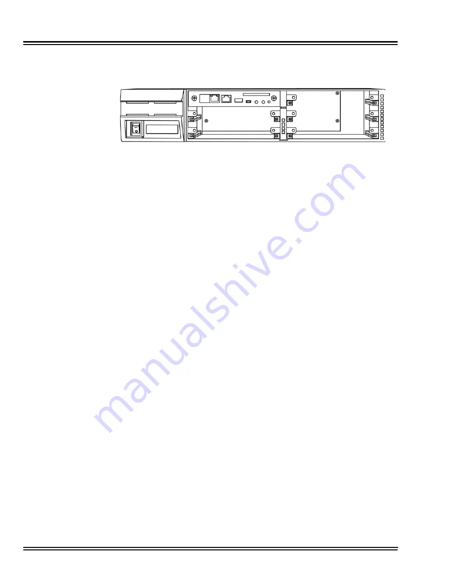
Figure 3-47 CD-CP00 Blade Installed
Содержание Univerge SV8100
Страница 1: ...System Hardware Manual Issue 4 1 February 2011...
Страница 2: ...THIS PAGE INTENTIONALLY LEFT BLANK...
Страница 36: ...Issue 4 1 UNIVERGE SV8100 1 14 Introduction to SV8100...
Страница 40: ...Issue 4 1 UNIVERGE SV8100 2 4 SV8100 System Specifications Figure 2 1 SV8100 System Block Diagram...
Страница 68: ...Issue 4 1 UNIVERGE SV8100 2 32 SV8100 System Specifications...
Страница 75: ...UNIVERGE SV8100 Issue 4 1 System Hardware Manual 3 7 Figure 3 7 Install Wall Mount Brackets with Screws...
Страница 99: ...UNIVERGE SV8100 Issue 4 1 System Hardware Manual 3 31 Figure 3 34 Install Screws Option 2...
Страница 148: ...Issue 4 1 UNIVERGE SV8100 3 80 Installing the SV8100 Chassis...
Страница 191: ...UNIVERGE SV8100 Issue 4 1 System Hardware Manual 4 43 Figure 4 15 Connecting a IPLA Daughter Board to a Network PC...
Страница 207: ...UNIVERGE SV8100 Issue 4 1 System Hardware Manual 4 59 Figure 4 22 Installing the PZ 8LCE Daughter Board...
Страница 247: ...UNIVERGE SV8100 Issue 4 1 System Hardware Manual 4 99 Figure 4 34 Control Signal Connection...
Страница 258: ...Issue 4 1 UNIVERGE SV8100 4 110 Installing the SV8100 Blades NOTES...
Страница 335: ...UNIVERGE SV8100 Issue 4 1 System Hardware Manual 5 77 Figure 5 92 Bluetooth Handset Controls and Indicators...
Страница 354: ...Issue 4 1 UNIVERGE SV8100 5 96 Installing DT300 DT700 Series DTL ITL Digital and IP Multiline Terminals...
Страница 360: ...Issue 4 1 UNIVERGE SV8100 6 6 Installing SV8100 Optional Equipment Figure 6 5 PGD 2 U10 ADP Connection Diagram...
Страница 367: ...UNIVERGE SV8100 Issue 4 1 System Hardware Manual 6 13 Figure 6 11 Setting the PGD 2 U10 ADP for a Door Box...
Страница 368: ...Issue 4 1 UNIVERGE SV8100 6 14 Installing SV8100 Optional Equipment Figure 6 12 Installing a Door Box...
Страница 380: ...Issue 4 1 UNIVERGE SV8100 6 26 Installing SV8100 Optional Equipment Figure 6 17 PGD 2 U10 ADP Connections...
Страница 417: ...UNIVERGE SV8100 Issue 4 1 System Hardware Manual 6 63 Figure 6 64 Power Failure Connector CN3 Shown on CD 4COTA Blade...
Страница 418: ...Issue 4 1 UNIVERGE SV8100 6 64 Installing SV8100 Optional Equipment...
Страница 419: ...THIS PAGE IS INTENTIONALLY LEFT BLANK...


