A-10 Connector Pin Assignments
RISER CARD CONNECTOR LOCATIONS
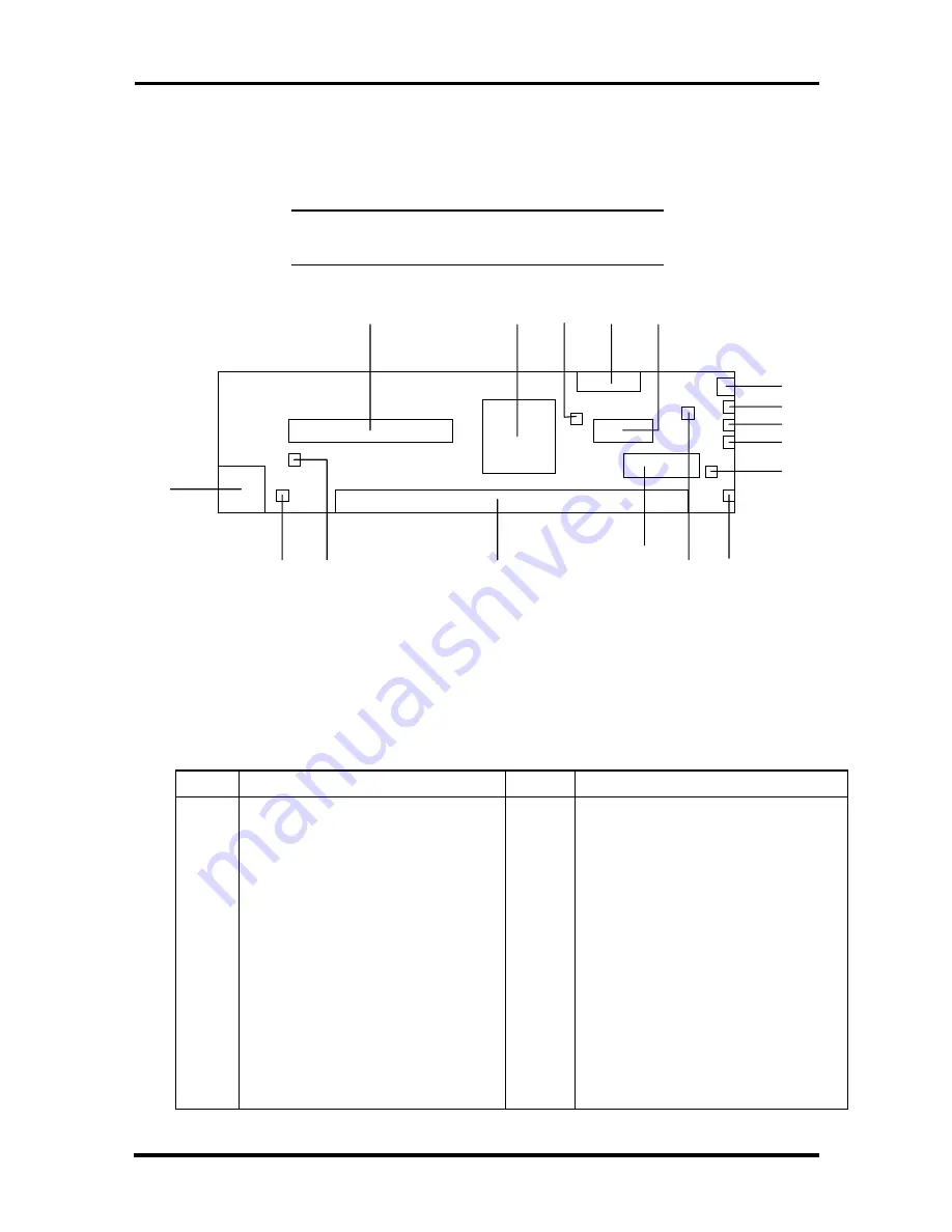
Figure A-7 shows the locations of connectors on the riser card.
NOTE:
Not all of the riser card connectors and
functions are used in all configurations.
Figure A-7 Riser Card Component and Connector Locations
The following table describes the riser card components and connectors shown in the
previous figure.
Table A-10 Riser Card Connectors and Components
Letter
Description
Letter
Description
A
PCI Connector (J3C1)
J
Modem Remote Wake Up
B
Intel PRO100B LAN Controller
K
Fan Header (J4L2)
C
Fan Speed Control Jumper (J3G1)
L
Front Panel System Reset Header
(J2L2)
D
Floppy Connector
M
Diskette Drive Connector (J2H1)
E
Power Connector (J3J1)
N
NLX System Board Connector (J4G1)
F
Power On Switch (J2L1)
O
LAN Enable/Disable Jumper (J3B1)
G
Power/Sleep/Off LED
(Green/Yellow/Off)
P
Card Remote Wake-Up (J4B1)
H
HDD Activity LED (Green)
Q
RJ-45 LAN Connector (J4A1)
I
LAN Activity LED (Green)
R
IDE Connector (J4J1)
A
Q
P
O
N
M
L
K
J
I
H
G
F
E
D
C
B
R
F
G
H
I
J
K
L
M
Содержание POWERMATE ENTERPRISE NETPC - SERVICE
Страница 6: ...Abbreviations xvii ...


