NI UMI-7774/72 User Guide and Specifications
24
ni.com
Encoder
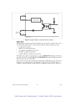
The UMI-7774/72 works only with encoders that have differential line or complementary driver outputs.
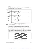
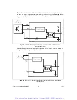
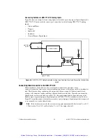
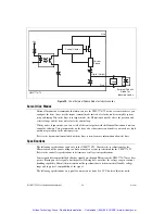
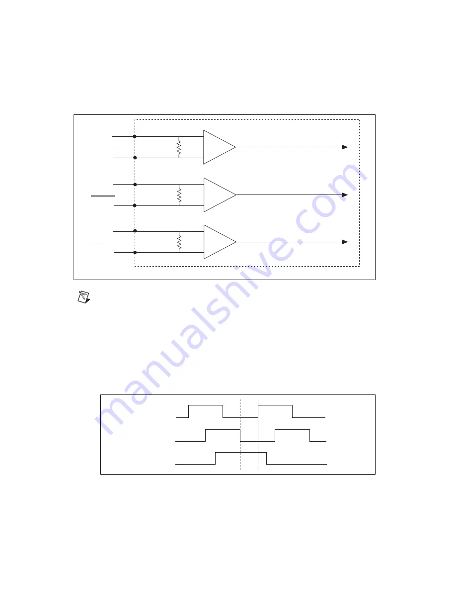
Refer to Figure 21 for an illustration of the encoder input interface circuit. The UMI-7774/72 supports
differential inputs for Phase A, Phase B, and Index signals.
Figure 21.
UMI-7774/72 Encoder Input Interface Circuit
Note
The UMI-7774/72 does
not
support single-ended encoders.
The differential encoder signals are converted to single-ended signals by a differential-to-single-ended
converter on the UMI-7774/72 and are then passed through to the NI 73xx motion controller.
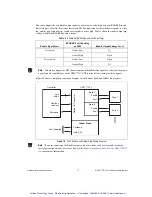
You can accommodate encoders with various phase relationships by swapping the signal connections
and/or connecting them to the inverting inputs as required by the application. A +5 V output, generated
by the UMI-7774/72 internal power supply, is also available on the connector for powering encoders.
This output provides 1 A maximum output current shared between Control connector pin 3, Feedback
connector pins 4 and 8, and Trigger/Breakpoint connector pin 3. Figure 22 shows the default encoder
phasing for NI 73xx motion controllers. Use Measurement & Automation Explorer (MAX) or the
NI-Motion driver software to configure the motion controller encoder input signals.
Figure 22.
Encoder Signal Phasing, CW (Forward) Direction
+
–
120
Ω
Phase A
Phase A
Phase A
+
–
120
Ω
Phase B
Phase B
Phase B
+
–
120
Ω
Index
Index
UMI-7774/72
Index
Phase A
Phase B
Index
Artisan Technology Group - Quality Instrumentation ... Guaranteed | (888) 88-SOURCE | www.artisantg.com

