USER GUIDE AND SPECIFICATIONS
NI UMI-7774/7772
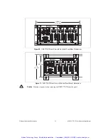
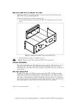
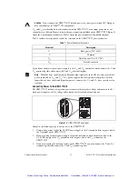
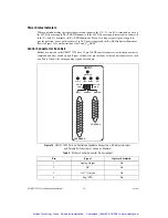
This document provides information about the National Instruments Universal Motion Interface
(UMI)-7774/7772 functionality and includes instructions for getting started, specifications, connection
requirements, and safety information.
Contents
Introduction.......................................................................................................................................... 2
Features ........................................................................................................................................ 2
Safety Information ............................................................................................................................... 4
Electromagnetic Compatibility Information ........................................................................................ 5
Related Documentation........................................................................................................................ 6
Installation ........................................................................................................................................... 6
Required Materials....................................................................................................................... 6
Optional Equipment ..................................................................................................................... 7
Unpacking and Installing the UMI-7774/72................................................................................ 7
Noise Considerations ................................................................................................................... 9
Mounting the UMI-7774/72................................................................................................................. 9
Mounting the UMI-7774/72 on a DIN Rail ................................................................................. 10
Mounting the UMI-7774/72 on a Panel ....................................................................................... 11
Mounting the UMI-7774/72 in a Standard 19 in. Rack ............................................................... 14
Connector Descriptions........................................................................................................................ 14
Power Input Terminal Block........................................................................................................ 14
Connecting Power To the UMI-7774/72 ............................................................................. 15
Power Status Indicators ............................................................................................................... 16
Control Connector for Each Axis ................................................................................................ 16
Analog Output...................................................................................................................... 17
Step (CW) and Dir (CCW) .................................................................................................. 17
Voltage Considerations for the UMI-7774/72 ..................................................................... 17
Fault ..................................................................................................................................... 18
Enable Output ...................................................................................................................... 20
Feedback Connector for Each Axis ............................................................................................. 22
Encoder ................................................................................................................................ 24
Limit and Home Inputs ........................................................................................................ 25
Limit and Home Status Indicators ....................................................................................... 27
Global Stop .................................................................................................................................. 28
Inhibit All............................................................................................................................. 28
Shutdown ............................................................................................................................. 28
Analog Input ................................................................................................................................ 28
Trigger/Breakpoint....................................................................................................................... 29
Trigger ................................................................................................................................. 29
Breakpoint............................................................................................................................ 29
General-Purpose Digital I/O ........................................................................................................ 30
Connecting Switches to UMI-7774/72 Sinking Inputs........................................................ 33
Connecting Inductive Loads to the UMI-7774/72 ....................................................................... 33
Artisan Technology Group - Quality Instrumentation ... Guaranteed | (888) 88-SOURCE | www.artisantg.com


