NI UMI-7774/72 User Guide and Specifications
22
ni.com
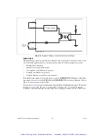
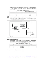
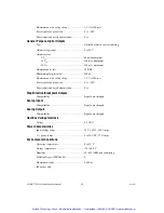
The Enable output circuit provides a current source to an external device. The maximum output current
for the Enable output depends on the V
iso
voltage. Refer to Table 4 for the maximum output current at
different V
iso
voltages.
Note
If the load current exceeds the over current trip point, the output shuts off.
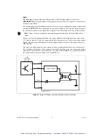
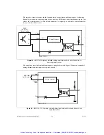
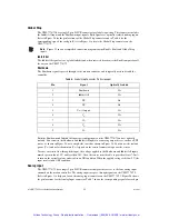
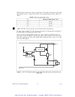
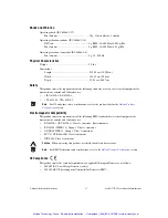
The output voltage is within 1.2 V of the voltage provided on the V
iso
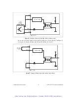
power supply. Refer to Figure 20
for an illustration of the Enable output interface circuit.
Figure 20.
UMI-7774/72 Optically Isolated Digital Output Circuit and Connection to an External Device
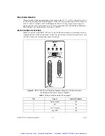
Feedback Connector for Each Axis
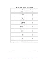
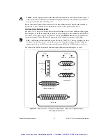
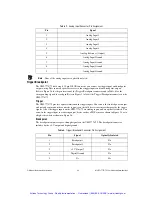
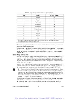
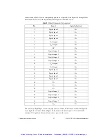
Each axis connected to the UMI-7774/72 has a 25-pin D-SUB feedback connector to which you can wire
incremental encoders, limits, and home sensors. Figure 14 shows the pin locations of the feedback
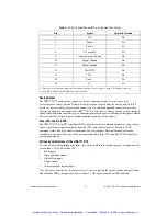
connector for each axis. Table 5 shows the corresponding signals for each pin.
Table 4.
Maximum Available Output Current
V
iso
Maximum Output Current (mA)
30 V
160 mA
24 V
150 mA
5 V
60 mA
Table 5.
Per Axis Feedback Connector Pin Assignment
Pin
Signal
Optically Isolated
1
Encoder Phase A
No
2
Encoder Phase B
No
Digital
Output
Viso
Ciso
Vcc
Load
Current Limiter
Current
Sense
UMI-7774/72
Artisan Technology Group - Quality Instrumentation ... Guaranteed | (888) 88-SOURCE | www.artisantg.com

