NI UMI-7774/72 User Guide and Specifications
30
ni.com
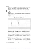
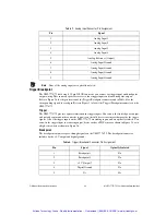
Refer to the appropriate National Instruments motion controller documentation for information about
trigger inputs and breakpoint outputs.
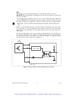
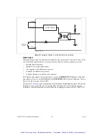
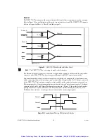
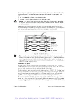
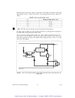
To cause current to flow through the input, the voltage applied to the trigger inputs must be greater than
3.5 V and less than 30 V. Also, the source must be able to provide at least 7.2 mA to turn on the optical
isolator and result in an ON condition. When the applied voltage is below 2 V, the input results in an
OFF condition.
General-Purpose Digital I/O
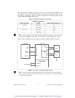
The UMI-7774/72 routes 16 of the general-purpose digital I/O lines of the National Instruments motion
controller to a single 25-pin D-SUB connector. All 16 digital I/O signals are optically isolated on the
UMI-7774/72. These signals are configurable as inputs and/or outputs on the National Instruments
motion controller. Use MAX or the NI-Motion driver software to configure the bits on port 1 as inputs
and the bits on port 2 as outputs.
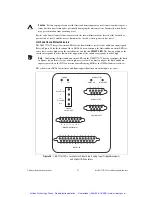
To access the 16 (eight inputs and eight outputs) digital I/O signals on the National Instruments motion
controller, connect one end of an additional SHC68-C68-S cable to the 68-pin digital I/O connector on
the motion controller and the other end to the 68-pin digital I/O connector on the UMI-7774/72.
Note
To access all of the 32 digital I/O signals on the motion controller, you can connect the digital
I/O connector on the motion controller to other National Instruments accessories. For example, you
can connect the digital I/O on the National Instruments motion controller to an SSR cable adapter
and then connect that adapter to the National Instruments SSR Series backplanes for use with other
National Instruments devices, such as DAQ devices. In this case, you do not typically connect
anything to the UMI-7774/72 digital I/O connector.
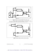
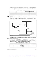
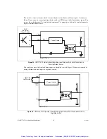
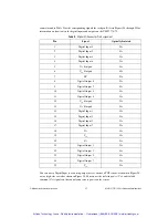
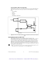
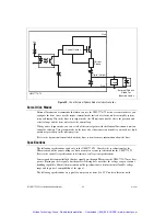
The 8 bits from the first port on the motion controller (Port 1: bits 0–7) become sinking inputs on the
UMI-7774/72, and the 8 bits from the second port of the motion controller (Port 2: bits 0–7) become
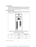
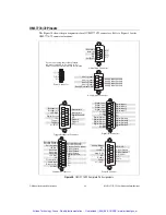
sourcing outputs on the UMI-7774/72. Refer to Figure 26 for the pin locations of the Digital I/O
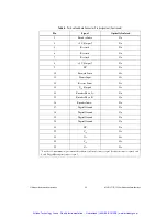
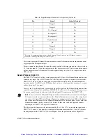
6
Trigger 1
Yes
7
Trigger 3
Yes
8
V
iso
(Output)
Yes
9
Breakpoint 2
No
10
Breakpoint 4
No
11
Digital Ground
No
12
NC
No
13
Trigger 2
Yes
14
Trigger 4
Yes
15
C
iso
Yes
†
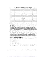
Provides 1 A maximum output current, shared between Control connector pin 3, Feedback connector
pins 4 and 8, and Trigger/Breakpoint connector pin 3.
Table 8.
Trigger/Breakpoint Connector Pin Assignment (Continued)
Pin
Signal
Optically Isolated
Artisan Technology Group - Quality Instrumentation ... Guaranteed | (888) 88-SOURCE | www.artisantg.com

