©
National Instruments Corporation
39
NI UMI-7774/72 User Guide and Specifications
UMI-7774/72 Pinouts
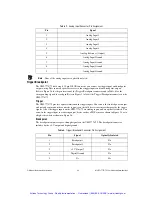
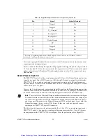
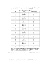
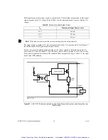
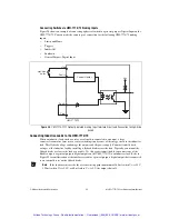
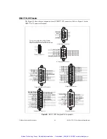
The Figure 30 shows the pin assignments for all UMI-7774/72 connectors. Refer to Figure 1 for the
UMI-7774/72 connector locations.
Figure 30.
UMI-7774/72 Complete Pin Assignments
Power Connector
V
C
V
iso
C
iso
If you are not using the isolation feature,
you must connect V to V
iso
and C to C
iso
.
Refer to the User Guide for more information.
Feedback Connector
Analog Output
NC
+5V OUT
Step (CW)
NC
Enable
Fault+
V
iso
(OUT)
AO GND
Digital Ground
Digital Ground
Dir (CCW)
NC
Fault–
C
iso
9
10
11
12
13
14
15
1
2
3
4
5
6
7
8
1
2
3
4
5
6
7
8
9
10
11
12
13
14
15
16
17
18
19
20
21
22
23
24
25
NC
Encoder Phase A
Encoder Phase B
Encoder Index
+5V OUT
Reserved
Reserved
Reserved
+5V OUT
NC
Forward Limit
Home Input
Reverse Limit
V
iso
OUT
Encoder Phase A–
Encoder Phase B–
Encoder Phase Index–
Digital Ground
Digital Ground
Digital Ground
Digital Ground
C
iso
C
iso
C
iso
C
iso
Shutdown
Inhibit All
NC
NC
C
iso
V
iso
(OUT)
6
7
8
9
1
2
3
4
5
Control Connector
C
iso
C
iso
C
iso
Global Stop Connector
Analog Input 1
Analog Input Ground
Analog Reference OUT
6
7
8
9
1
2
3
4
5
Analog Input Connector
Analog Input 2
Analog Input 3
Analog Input 4
Analog Input Ground
Analog Input Ground
Analog Input Ground
Breakpoint 1
Breakpoint 3
+5V OUT
Digital Ground
C
iso
Trigger 1
Trigger 3
V
iso
(OUT)
Breakpoint 2
Breakpoint 4
Digital Ground
NC
Trigger 2
Trigger 4
C
iso
9
10
11
12
13
14
15
1
2
3
4
5
6
7
8
Trigger/Breakpoint Connector
Digital I/O Connector
1
2
3
4
5
6
7
8
9
10
11
12
13
14
15
16
17
18
19
20
21
22
23
24
25
Digital Output 1
Digital Input 0
Digital Input 2
Digital Input 4
Digital Input 6
V
iso
OUT
NC
Digital Output 0
Digital Output 2
Digital Output 4
Digital Output 6
V
iso
OUT
Digital Input 1
Digital Input 3
Digital Input 5
Digital Input 7
C
iso
C
iso
C
iso
C
iso
V
iso
OUT
V
iso
OUT
Digital Output 3
Digital Output 5
Digital Output 7
Artisan Technology Group - Quality Instrumentation ... Guaranteed | (888) 88-SOURCE | www.artisantg.com

