background image

GT10/GT30

6.2

Entering Configuration Settings with GTWIN

103

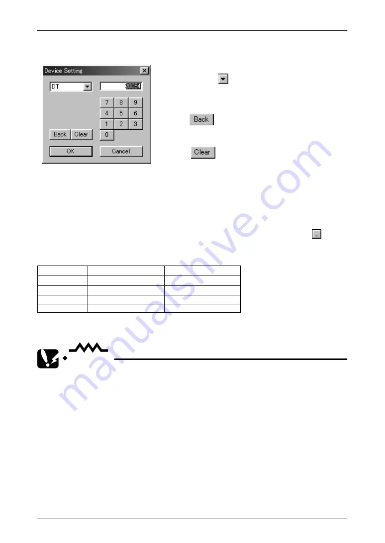
Device Setting dialog box

The           button functions as a backspace
key when entering addresses.

The            button acts as a Clear key.

Click on the       button to display the pull–down
menu, and select the device from that menu.
Enter the address using the ten–keys.

Transfer Outside
Clock data displayed in the GT30 can be transferred to an external device such as a
PLC, using this setting.

Off ––– The GT30 clock data is not transferred to an external device.

On ––– The GT30 clock data is transferred to an external device.

If “On” is selected for the above “Transfer Outside” parameter, click on the 

 button

to specify the output destination and the initial device, and specify the address.

Data storage sequence for internal PLC device

Upper byte

Lower byte

Top address

Minutes data (H00 to H59)

Second data (H00 to H59)

Top a1

Day data (H01 to H31)

Hour data (H00 to H23)

Top a2

Year data (H00 to H99)

Month data (H01 to H12)

Top a3

Day data (H00 to H06)

*In the day data, H00 indicates Sunday and H06 indicates Saturday.

CAUTION

If “On” is selected for the “Transfer Outside” parameter, the data will
be transferred to the DT90054 as the default device. If this device
address does not exist in the PLC connected to the GT30, however,
re–specify the address so that it matches the model connected to the
GT30.
Selecting a device address that does not exist in the PLC will cause an
error (ER61) to occur.

Backlight control

Auto–Off

This is used to specify the Auto–Off backlight feature.

Off ––– The Auto–Off backlight feature is not used.

On ––– Auto–Off backlight feature is used. This parameter specifies the period of time
that the GT30 is inactive before the backlight goes off automatically.

Содержание GT10

Страница 1: ...T1F340V1 1EN 5 2003 is a global brand name of Matsushita Electric Works Includes installation guide for GTWIN screen creation software Applicable Models GT10 Ver 1 Ver 2 GT30 AUTOMATECH Sp z o o www a...

Страница 2: ...ife or which may cause severe injury or damage Designs should include safety mechanisms for use in the event that switch functions do not function correctly w Do not use this product in an environment...

Страница 3: ...ications between the units Chapter 5 GT10 Configuration Settings This chapter describes the configuration settings for the GT10 and how they should be entered Chapter 6 GT30 Configuration Settings Thi...

Страница 4: ...1 1 3 Functions 2 1 1 4 Touch Key 3 1 1 5 Memory 1 3 1 1 6 Memory 2 3 1 1 7 Interface 4 1 2 GT10 Names and Functions of Parts 5 1 2 1 GT10 front 5 1 2 2 GT10 rear 5 1 2 3 Names and Functions of Parts...

Страница 5: ...4 Setting the Basic Communication Area GT30 and PLC 37 3 4 1 What is the Basic Communication Area 37 3 4 2 GT30 Basic Communication Area Map 38 Chapter 4 Connecting and Communicating with the PLC 4 1...

Страница 6: ...tings Auto Paging 77 5 2 5 GT Configuration Settings Startup Screen Settings 79 5 2 6 GT Configuration Settings Setup 80 5 2 7 GT Configuration Settings Hold PLC Device 82 5 2 8 GT Configuration Setti...

Страница 7: ...rt 111 6 3 6 Setting Mode Memory Initialization Clear Memory 112 6 3 7 Test Mode Self Diagnosis 113 6 3 8 Inhibiting the System Menu Display 114 Chapter 7 How the Various Functions Are Used 7 1 Switch...

Страница 8: ...Saving Screen Data Files 150 Chapter 10 Preparing GTWIN 10 1 Installing GTWIN 152 10 2 Booting GTWIN 158 10 2 1 Selecting the Working Menu 158 10 2 2 Selecting the Model 158 10 2 3 Entering Settings f...

Страница 9: ...Table of Contents GT10 GT30 viii...

Страница 10: ...ix Part I GT10 GT30 Main Unit...

Страница 11: ...x Before Using the GT10 GT30 This section describes items that should be confirmed and precautions that should be observed before the GT10 GT30 is used Make sure you read this section before using the...

Страница 12: ...gs please see page 42 and subsequent pages 4 Set up the main unit page 26 34 When the product is shipped from the factory it is set up with specifications that enable connection to the FP series PLC I...

Страница 13: ...software 8 Create the screen contents Create the screen contents using the Terminal GTWIN screen creation tool and send the screen to the GT main unit For information on creating screens and on operat...

Страница 14: ...attached to the front panel of the unit Installation instructions Please read these instructions carefully before using the product Communication connector Waterproof packing One piece of waterproof...

Страница 15: ...king has been attached to unit STN monochrome liquid crystal display type AIGT3100B STN color liquid crystal display type AIGT3300B CAUTION There is a film over the front panel protective sheet Remove...

Страница 16: ...lease read it carefully before using your product CAUTION About the software usage license agreement and user card Before using GTWIN read the Software usage license agreement carefully The license ag...

Страница 17: ...age 41 Chapter 4 Connecting and Communicating with the PLC Items Included with the Front Panel Protective Sheet AIGT180 AIGT380 Front panel protective sheet In order to protect the touch panel on the...

Страница 18: ...t No AIGT1000B Main unit Communication cable PLC connecting cable 1 For connection to TOOL port of FP0 FP2 FP2SH FP M Mini DIN 5 pin loose wire cable 2 m 6 56 ft Product No AIGT8192 Connecting to the...

Страница 19: ...nnecting to the COM port of the FP0 Because connecting the unit to the COM port of the FP FP0 requires a loose wire connection this cable is not available For more detailed information please see Conn...

Страница 20: ...10 for replacement Ten in set 1 sheet included with GT10 when shipped AIGT180 protective sheet Front panel protective sheet for GT30 for replacement Ten in set 1 sheet included with GT30 when shipped...

Страница 21: ...e or which may cause severe injury or damage Designs should include safety mechanisms for use in the event that switch functions malfunction Do not use this product in an environment where combustible...

Страница 22: ...such as duplicate circuits wherever possible 3 The quality of this product is guaranteed for one year after purchase and this guarantee is limited to the range of items stated in these specifications...

Страница 23: ...Safety Precautions GT10 GT30 xxii...

Страница 24: ...Chapter 1 Specifications...

Страница 25: ...status Dustproof and drip proof from front panel only packing used on panel contact sur face When reattaching replace waterproof packing Mass Approx 260 g 9 171 oz Approx 440 g 15 519 oz 1 1 2 Display...

Страница 26: ...ed software and PLC set automatically by connecting cable Debugging functions Through function PLC can be debugged from personal computer by connecting com puter to TOOL port and PLC to COM port Scree...

Страница 27: ...Port Conditions for communications with external devices Data bits 7 or 8 bits Parity None Odd Even Stop bits 1 bit Protocol FP series supported general purpose RS232C supported Connector Connector te...

Страница 28: ...ction port 1 communication connector provided as accessory when when unit is shipped Waterproof packing 1 piece is attached to unit when unit is shipped TOOL port connection port for GTWIN screen crea...

Страница 29: ...rnal secondary battery which is charged when the power supply is turned on The operation mode setting switches control the ON OFF settings for the secondary battery backup function the ability to shif...

Страница 30: ...t is shipped Tool port connection port for GTWIN screen creation tool Operation mode setting switches Waterprrof packing 1 piece is attached to unit when unit is shipped 3 4 5 7 6 1 3 3 Names and Func...

Страница 31: ...nd other functions Switch no Function OFF ON 1 Usage inhibited Should always be in the OFF position when unit is used 2 Inhibits system menu shift Shift possible Shift inhibited 3 Usage inhibited Shou...

Страница 32: ...re is no need to wire both the RS and CS Wiring and cables should be laid out in such a way that cables are not affected by external noise Also shielded wiring should be used for cables 1 4 2 TOOL Por...

Страница 33: ...MC Directive EMC Direc tive 89 336 EEC the GT10 conforms to European Stan dards EN50081 2 1993 EN50082 2 1995 As a condi tion of compatible a ferrite core should be installed when wiring to the termin...

Страница 34: ...nsions 11 1 5 Dimensions 1 5 1 GT10 Dimensions 144 5 67 32 1 26 138 0 5 43 80 3 15 4 0 16 97 3 82 60 2 36 40 1 57 72 2 83 65 8 2 59 9 6 0 38 7 0 28 8 5 0 33 2 0 08 Unit mm inch Display unit Display un...

Страница 35: ...0 are as shown below 5 47 2 64 0 0 Applicable panel thickness 1 0 to 6 0 0 002 to 0 236 Unit mm inch 1 1 139 0 0 04 67 0 0 04 1 5 3 GT30 Dimensions 177 6 97 38 0 1 50 4 4 0 17 158 2 6 23 126 8 4 99 11...

Страница 36: ...imensions 13 1 5 4 GT30 Panel Cutout Dimensions The panel cutout dimensions of the GT30 are as shown below 5 93 4 69 0 0 Applicable panel thickness 1 0 to 5 0 0 039 to 0 197 Unit mm inch 1 1 150 5 0 0...

Страница 37: ...GT10 GT30 1 5 Dimensions 14...

Страница 38: ...Chapter 2 Installation and Wiring...

Страница 39: ...display unit from rising Locations where condensation may form because of sudden fluctuations in temperature Locations where flammable or corrosive gases are present Locations where there are high co...

Страница 40: ...fe of the internal battery will be radically shortened if used continually in ambient operating temperatures of more than 40 C 104 F 50 C 122 F for the GT30 or when the operating voltage exceeds 25V D...

Страница 41: ...ess of 1 0 mm to 6 0 mm should be used Installation angle If the installation angle is between 60 degrees and 0 degrees horizontal the operating voltage should be set to 25V DC or lower Installationan...

Страница 42: ...he screws too hard can cause deformation of the front panel so that the switch will not function properly Make sure screws are tightened to the appropriate degree Applicable panel thickness A panel wi...

Страница 43: ...ation 20 clearance of 30 mm to 50 mm 1 18 inch to 1 97 inch around the GT30 This prevents cables from being damaged and facilitates the installation work Also make sure that the slits in the main unit...

Страница 44: ...rcuit is being used power should always be supplied to the GT series through a fuse or a similar protective device Keep the power supply voltage within the operating voltage range Operating voltage ra...

Страница 45: ...ring the Power Supply 22 Keep the power supply wiring separate Wiring to the GT series PLC and other power equipment should have separate wiring systems PLC GT series Breaker Power equipment Insulated...

Страница 46: ...d sleeves If stick type terminals are used the models listed below are marketed by Fenics Contact Co Ltd Maker Cross Section Surface Size Fenics Co Model 0 25 mm2 AGW 24 AI 0 25 to 6 YE Fenics Contact...

Страница 47: ...thout twisting the core wire The core wire should be connected without soldering it Vibration can sometimes cause soldered connections to break loose After connecting the wiring avoid subjecting the c...

Страница 48: ...Chapter 3 Setup...

Страница 49: ...tion speed 19200 bits s data length 8 bits stop bit 1 bit parity odd Communication error temporary processing Retries 3 error code displayed not held parameter settings TOOL port Communication speed 1...

Страница 50: ...e from GTWIN Boot GTWIN and select Transfer on the File menu When the transfer function is selected a dialog box for file transfer is displayed At this point specify the type of data to be transferred...

Страница 51: ...10 Configuration file being transferred Screen transfer cable AFC8513D 4 Setup is completed If the transfer has been completed without any problems the setup is completed CAUTION Backup of the GT10 Co...

Страница 52: ...ord devices DT FL etc 3 consecutive words Bit devices WR etc 3 consecutive words Word devices For reading devices handled in word units 3 consecutive words Bit devices For reading devices handled in b...

Страница 53: ...t the device for which settings are to be entered Use the ten keys to enter the address The button acts as a backspace key when entering an address and the button functions as a Clear key 3 2 2 GT10 B...

Страница 54: ...on the screen specified by the PLC is forcibly displayed This is executed only when at the rise of the bit Backlight Valid flag When the bit is turned on the backlight flashing backlight color contro...

Страница 55: ...ify movements and reference and set data Output destination relay Bit configuration Address F E D C B A 9 8 7 6 5 4 3 2 1 0 System switch out put destination Function switch out put destination Displa...

Страница 56: ...GT10 GT30 3 2 Setting the Basic Communication Area GT10 and PLC 33 System switches should be replaced with keyboard parts and function switches with switch parts...

Страница 57: ...eed 19200 bits s data length 8 bits stop bit 1 bit parity odd Communication error temporary processing Retries 3 error code displayed not held parameter settings TOOL port Communication speed 19200 bi...

Страница 58: ...e from GTWIN Boot GTWIN and select Transfer on the File menu When the transfer function is selected a dialog box for file transfer is displayed At this point specify the type of data to be transferred...

Страница 59: ...ration file being transferred Screen transfer cable AFC8513D 4 Setup is completed If the transfer has been completed without any problems the setup is completed CAUTION Backup of the GT30 Configuratio...

Страница 60: ...ord devices DT FL etc 3 consecutive words Bit devices WR etc 3 consecutive words Word devices For reading devices handled in word units 3 consecutive words Bit devices For reading devices handled in b...

Страница 61: ...t the device for which settings are to be entered Use the ten keys to enter the address The button acts as a backspace key when entering an address and the button functions as a Clear key 3 4 2 GT30 B...

Страница 62: ...age prohibited N 2 BAT LOW flag BAT Data Input In Progress flag Explanation of system areas BZ This turns on the buzzer Forced Display flag At the rise when the bit is turned on the screen specified b...

Страница 63: ...GT10 GT30 3 4 Setting the Basic Communication Area GT30 and PLC 40...

Страница 64: ...Chapter 4 Connecting and Communicating with the PLC...

Страница 65: ...ta length 8 bits 414 Data length 8 bits Parity check Yes Odd Parity check Yes Odd Stop bits 1 bit Stop bits 1 bit Line return code CR Line return code CR Start code No STX Start code No STX 415 COM Po...

Страница 66: ...ss section surface area 0 08 mm2 to 1 25 mm2 should be used for connections For wiring procedures please refer to Wiring the COM Port on page 23 4 1 2 Connecting to the TOOL Port AIGT8192 GT10 FP TOOL...

Страница 67: ...RD White 4 5 Specifications L Product No Mini DIN 5 pin Single side loose wire 2m AIGT8192 Connecting to the FP TOOL port GT10 GT30 3 5 4 1 2 No 1 brown Pin no on PLC side No 3 green or orange No 2 wh...

Страница 68: ...ing Odd Stop bits 1 bit Line return code CR Start code No STX 414 Baud rate setting 19200 bits s H0 00 415 Unit number 1 K1 416 Modem connection No connection H0 Connecting to the FP0 COM port GT10 GT...

Страница 69: ...cation format settings System register no Item Value Set System register value 410 Unit number 1 K1 411 Data length 8 bits H0 Modem connection No connection 414 Baud rate setting 19200 bits s H010X X...

Страница 70: ...onnecting to the FP0 TOOL port GT10 GT30 3 5 4 1 2 No 1 brown Pin no on PLC side No 3 green or orange No 2 white or red PLC side Pin no Abbreviation 1 SG 2 SD 3 RD 4 5 Abbreviation GT main unit side P...

Страница 71: ...K0 415 Unit number 1 K1 416 Modem connection No connection H0 PLC communication cable D sub 9 pin loose wire cable AIP81842D 1 2 3 4 5 6 7 8 9 Signals on D sub side Pin no Wire color GT COM port 1 2...

Страница 72: ...s 415 Unit number 1 416 Modem connection No connection PLC communication cable D sub 9 pin loose wire cable AIP81842D 1 2 3 4 5 6 7 8 9 Signals on D sub side Pin no Wire color GT COM port 1 2 White RD...

Страница 73: ...ommunication cable Mini DIN 5 pin loose wire cable AIGT8192 3 5 4 1 2 5mm 35mm 2000mm Mini DIN plug side signals 1 SG Brown 2 SD Green 3 RD White 4 5 Pin no Abbreviation Wire color Specifications L Pr...

Страница 74: ...fixed at 1 bit PLC communication cable D sub 9 pin loose wire cable AIP81842D 1 2 3 4 5 6 7 8 9 Signals on D sub side Pin no Wire color GT COM port 1 2 White RD 3 Green SD 4 5 6 7 Brown GND 8 9 Specif...

Страница 75: ...OOL port Memory COM setting port Setting contents Transfer speed Data length Modem control Program memory protect Program memory select Transfer speed Value Set Not related to GT10 communication 19200...

Страница 76: ...length Modem control Program memory protect Program memory select Transfer speed Value Set 19200 bits s 8 bits No Not related to GT10 communication Switch status OFF ON OFF DIP SW 2 FP10SH CPU TOOL p...

Страница 77: ...to the FP10SH TOOL port 1 FG SD RS SG CS RD 2 3 4 5 6 N C 7 8 9 N C ER SD SD RD CS GND RS RD RS CS GND 1 2 3 4 5 6 7 8 9 GT10 GT30 Pin no on PLC side No 3 green No 2 white No 7 brown PLC side GT main...

Страница 78: ...rol signals CS RS invalid OFF PLC communication cable D sub 9 pin loose wire cable AIP81842D 1 2 3 4 5 6 7 8 9 Signals on D sub side Pin no Wire color GT COM port 1 2 White RD 3 Green SD 4 5 6 7 Brown...

Страница 79: ...ts K3 Parity check Yes Parity setting Odd Stop bits 1 bit Line return code CR Start code No STX 414 Baud rate setting 19200 bits s K0 415 Unit number 1 K1 416 Modem connection No connection H0 PLC com...

Страница 80: ...tem Value Set System register value 410 Unit number 1 K1 411 Data length 8 bits H0 Modem connection No connection PLC communication cable Mini DIN 5 pin loose wire cable AIGT8192 3 5 4 1 2 5mm 35mm 20...

Страница 81: ...Communication Error on GTWIN For information on how settings are entered please refer to page 75 GT10 and page 97 GT30 EXPLANATION Conditions when the automatic settings mode is in effect If communica...

Страница 82: ...the PLC will not be possible if the target usage of the RS232C port has been set to Computer Link Always set the setting on the PLC side to match Computer Link For detailed information please refer to...

Страница 83: ...ter being used to edit the GT series screens and the PLC pro grams can be edited and monitored via the GT series PLC debugging CAUTION Precautions when using the through function The system should be...

Страница 84: ...GT10 GT30 4 10 Through Function 61 FP Programmer II on an ongoing basis GT10 GT30 FP Programmer II 25V DC max...

Страница 85: ...nnected to the FX series Setting the communication conditions Setting the communication conditions for the GT main unit The following settings should be entered for the COM port communication conditio...

Страница 86: ...ge Please refer to the instruction manual of the PLC being used for detailed information If input relays output relays and auxiliary relays are being used in word units addresses should be specified i...

Страница 87: ...SD SD RD RD RS RS CS CS GND GND GT main unit side Pin no Abbreviation 6 7 SG 20 ER GT10 GT30 C200HS C200H LK201 1 C120 LK201 V1 2 1 FG 2 SD 3 RD 4 RS 5 CS D sub 25 pin on Omron PLC side Pin no Abbrev...

Страница 88: ...no Abbreviation 1 FG 2 SD 3 RD 4 RS 5 CS Pin no Abbreviation 6 7 SG 8 9 C120 C120F C120 LK201 V1 2 1 FG 2 SD 3 RD 4 RS 5 CS D sub 25 pin on Omron PLC side Pin no Abbreviation SD SD RD RD RS RS CS CS G...

Страница 89: ...provided with the CQM1 CPU11 it cannot be used at the same time as a PLC SYSMAC series using link interface CPU Link I F Wiring diagram GT series C200HX CPU85 Z CPU64 CPU44 C200HE CPU42 C200HG CPU63 C...

Страница 90: ...no Abbreviation 6 7 SG 20 ER Communication port 1 connections GT10 GT30 1 FG 2 SD 3 RD 4 RS 5 CS D sub 9 pin on Omron PLC side Pin no Abbreviation SD SD RD RD RS RS CS CS GND GND GT main unit side Pin...

Страница 91: ...ion 6 7 SG 25 Connection cable for the peripheral port 25 pin CS1W SCU21 D sub 9 pin on Omron PLC side SD SD RD RD GT main unit side Pin no Abbreviation 1 FG 2 SD Pin no Abbreviation CS1W SCB21 RD RD...

Страница 92: ...HEX PLC main unit mode setting monitor mode DM6645 0001 HEX RS232C port mode setting higher order link DM6646 0004 HEX Communication conditions settings 19200 bits s 7 bits even 1 bit DM6668 0000 HEX...

Страница 93: ...tting higher order link DM6551 0004 HEX Communication conditions settings 19200 bits s 7 bits even 1 bit Devices that can be used Device type Address range Points Relay area 0000CH to 0252CH 253 words...

Страница 94: ...Chapter 5 GT10 Configuration Settings...

Страница 95: ...settings from the GT10 main unit page 85 Some of the settings such as the communication parameters the internal clock and adjustments of the liquid crystal display contrast can be set using the syste...

Страница 96: ...lect the GT Configuration sub menu under Configuration Configuration Settings GTWIN Configuration These are operating environment settings for GTWIN GT Configuration These are configuration settings f...

Страница 97: ...communication Modes Turn on the radio button for either GT10 Mode or IOP01 Mode GT10 Mode Select this if you are using the GT10 for the first time IOP01 Mode This mode is for users who are using a con...

Страница 98: ...n acts as a Clear key REFERENCE For detailed information on the basic communication area map see GT10 Basic Communication Area Map on page 30 EXPLANATION Standard settings Clicking on the button in th...

Страница 99: ...et can be selected Baud Rate Select 9600 19200 38400 57600 76 800 or 115200 bits s Data Length Select either 7 bits or 8 bits Stop Bits This is fixed at 1 bit Parity Bit Select None Odd or Even Handle...

Страница 100: ...r is eliminated For contents of error codes please see Error Codes and How to Handle Them on page 142 TOOL Port for GTWIN connection This is used to specify the communication speed and transmission fo...

Страница 101: ...paging and the Setup button is clicked a dialog box containing the following auto paging settings is displayed Clicking on the button for Screen No Time or Jump to displays a Value Set dialog box Set...

Страница 102: ...Set dialog box where the values can be specified Start up Screen No This specifies the number of the screen that will be displayed when the GT10 is booted Clicking on the button displays a Value Set...

Страница 103: ...uration Settings Setup Clicking on the Setup tab in the GT Configuration dialog box displays the screen shown below Here clock functions backlight control and other parameters can be specified Setup s...

Страница 104: ...device Upper byte Lower byte Top address Minutes data H00 to H59 Second data H00 to H59 Top address 1 Day data H01 to H31 Hour data H00 to H23 Top address 2 Year data H00 to H99 Month data H01 to H12...

Страница 105: ...GT10 screens as either invalid or valid Select one of the radio buttons Disable Touch sounds are disabled Enable Touch sounds are enabled 5 2 7 GT Configuration Settings Hold PLC Device Clicking on t...

Страница 106: ...internal PLC device the next time that the power supply is turned on If the power supply on the GT10 side is not turned on the data can be held for the period of time that the backup with the interna...

Страница 107: ...nction is set to Hold a Start No item is displayed Click on the button to display the value setting dialog box shown below and specify a starting number After the setting has been entered the contents...

Страница 108: ...to bring up the system menu 1 Touch the four corners of the LCD touch panel simultaneously Touch these four corners at the same time and continue pressing them for about one second 2 The initial scre...

Страница 109: ...to the GT10 Each time the Function key is pressed the Baud rate switches in the sequence of 9600 19200 38400 57600 76800 115200 bits s Set the speed to match that of the PLC connected to the GT10 Form...

Страница 110: ...ta length stop bits parity for the personal computer GTWIN connected to the GT10 The items displayed are Data length Stop bit Parity and each time the Function key is pressed the display switches in t...

Страница 111: ...me indicated by the internal clock of the GT10 Items can be changed by touching the item year month day date hour minute second and touching the and keys to change the values SHORTCUTS ADJUST Touching...

Страница 112: ...ounds and the memory is cleared When the buzzer stops sounding the memory has been completely cleared SHORTCUTS RETURN To complete the settings and return to the previous screen touch the ESC key CAUT...

Страница 113: ...ange Buzzer This runs an operation check of the buzzer LCD This displays a pattern and runs an operation check of the display Contrast Touch the and keys to check changes in the contrast SHORTCUTS RET...

Страница 114: ...o make it impossible to display the system menu Operation mode setting switches Switch no Function OFF ON 1 SRAM backup using secondary battery No Yes 2 Inhibits system menu shift Shift possible Shift...

Страница 115: ...GT10 GT30 5 3 Entering Configuration Settings from the GT10 92...

Страница 116: ...Chapter 6 GT30 Configuration Settings...

Страница 117: ...settings from the GT30 main unit page 108 Some of the settings such as the communication parameters the internal clock and adjustments of the liquid crystal display contrast can be set using the syst...

Страница 118: ...lect the GT Configuration sub menu under Configuration Configuration Settings GTWIN Configuration These are operating environment settings for GTWIN GT Configuration These are configuration settings f...

Страница 119: ...C The following explains how to specify a device in the PLC to be used for basic communication between the GT30 and the PLC Device used This specifies the internal PLC device used for basic communicat...

Страница 120: ...licking on the button in the GT Configuration dialog box displays the following message Clicking on OK sets the default values the configuration settings entered when the unit is shipped for all of th...

Страница 121: ...or 8 bits Stop Bits This is fixed at 1 bit Parity Bit Select None Odd or Even Handle Communication Error Clicking on the button displays the Communication Error Remedy dialog box This is used to speci...

Страница 122: ...or Codes and How to Handle Them on page 142 TOOL Port for GTWIN connection This is used to specify the communication speed and transmission format when the GT30 is connected to a personal computer GTW...

Страница 123: ...paging and the Setup button is clicked a dialog box containing the following auto paging settings is displayed Clicking on the button for Screen No Time or Jump to displays a Value Set dialog box Set...

Страница 124: ...e Set dialog box where the values can be specified Start up Screen No This specifies the number of the screen that will be displayed when the GT30 is booted Clicking on the button displays a Value Set...

Страница 125: ...ation Settings Setup Clicking on the Setup tab in the GT Configuration dialog box displays the screen shown below Here clock functions backlight control and other parameters can be specified Setup scr...

Страница 126: ...C device Upper byte Lower byte Top address Minutes data H00 to H59 Second data H00 to H59 Top address 1 Day data H01 to H31 Hour data H00 to H23 Top address 2 Year data H00 to H99 Month data H01 to H1...

Страница 127: ...in Touch Sounds This sets the touch sounds corresponding to GT30 screens as either invalid or valid Select one of the radio buttons Disable Touch sounds are disabled Enable Touch sounds are enabled De...

Страница 128: ...nd select the device from that menu Enter the address using the ten keys The button functions as a backspace key when entering addresses The button acts as a Clear key CAUTION Data for PLC devices hel...

Страница 129: ...e GT internal device hold function is turned off Hold The GT internal device hold function is turned on If the above setting for the GT internal device hold function is set to Hold a Start No item is...

Страница 130: ...internal devices Device type Address range Points Data register GDT0000 to GDT2047 2048 words Memory Internal relay WGR0000 to WGR0255 256 words Bits Internal relay GR0000 to GR255F 4096 points The WG...

Страница 131: ...menu 6 3 2 Bringing Up the System Menu The following procedure is used to bring up the system menu 1 Touch the four corners of the LCD touch panel simultaneously Touch these four corners at the same...

Страница 132: ...ajustment screen when using the monochrome type SHORTCUTS ADJUST Touching the key increases the contrast and touching the key decreases it RETURN To complete the settings and return to the previous s...

Страница 133: ...reases it SET Touching the SET key updates the Value Set and restarts the clock Touching the ADJUST key sets the seconds value of the current time to 00 A seconds value of 0 to 29 is rounded off to th...

Страница 134: ...should be set to 00 Bitrate GTWIN communication speed Each time the Function key is touched the Baud rate switches in the sequence of 9600 19200 115200 bits s Set the speed to match that of the person...

Страница 135: ...tings The default initial values for the TOOL Port communication parameter settings are 19200 bits s 8 1 Odd COM port communication parameter settings The default initial values for the COM port commu...

Страница 136: ...in the user memory F ROM of the main unit Before initializing the F ROM always save screen data to a floppy disk or another medium with GTWIN 6 3 7 Test Mode Self Diagnosis The self diagnosis is run f...

Страница 137: ...d to make it impossible to display the system menu Switch no Function OFF ON 1 Usage inhibited Should always be in the OFF position when unit is used 2 Inhibits system menu shift Shift possible Shift...

Страница 138: ...Chapter 7 How the Various Functions Are Used...

Страница 139: ...ea word device First word specifies screen no from PLC Second word usage prohibited area Third word no of screen currently displayed Internal PLC device Ongoing communication How screens are switched...

Страница 140: ...FPWIN GR X0 F 0 MV H 2 D T 0 No of screen displayed Address of first word in basic communication area word device Condition that displays screen 7 1 2 Switching the Screen with the GT Main Unit Using...

Страница 141: ...irst word the screen number specified by the PLC do not change For detailed information see page 120 2 Using the Value Set operation mode Select the Value Set operation mode and enter the following se...

Страница 142: ...ged Value Set dialog box If the value is entered with the button pressed as shown at the left a hexadecimal screen number is speci fied and if the value is entered with the button pressed a decimal va...

Страница 143: ...t device 1 At the same time that the PLC issues an instruction to change the screen again to Screen No 1 or shortly after that point the forced display flag in the first word Bit E of the basic commun...

Страница 144: ...GT10 GT30 7 1 Switching Screens 121 currently displayed screen to that of the new screen number and thus avoids the kind of case described above...

Страница 145: ...t is turned on the screen specified by the PLC is forcibly displayed This is executed only when at the rise of the bit Backlight Valid flag When the bit is turned on the backlight flashing backlight c...

Страница 146: ...is setting valid however Bit D Backlight Valid flag must always be turned on at the same time Bit status Backlight status C OFF Lighted ON Flashing Making the buzzer sound Bit F of the first word of t...

Страница 147: ...is executed only when at the rise of the bit Backlight Valid flag When the bit is turned on the backlight flashing backlight color control becomes effective Backlight Flashing 0 Lighted normal 1 Flash...

Страница 148: ...etting valid however Bit D Backlight Valid flag must always be turned on at the same time Bit status Backlight status C OFF Lighted ON Flashing Making the buzzer sound Bit F of the first word of the b...

Страница 149: ...GT10 GT30 7 3 GT30 Bit Device Functions 126...

Страница 150: ...Chapter 8 Servicing and Maintenance...

Страница 151: ...from the factory the No 1 operation mode setting switch is set to the OFF position Before turning on the power supply always set the No 1 operation mode setting switch on the back of the GT10 to the O...

Страница 152: ...ry be set to OFF for storage However please note that when the switch is set to OFF the clock data and the device hold area data will not be backed up 3 Service life shorten beyond all measure when us...

Страница 153: ...ays be removed before turning on the power supply Remove insulation sheet EXPLANATION Battery Performance Battery performance when operating at a normal temperature of 25 C a normal humidity of 65 RH...

Страница 154: ...AIGT380 Replacing the Front Panel Protective Sheet Follow the steps below to replace the sheet 1 Remove the attached front panel protective sheet First peel off the front panel protective sheet alread...

Страница 155: ...ckings for replacement set of 10 For GT10 AIGT181 For GT30 AIGT381 Replacing the Waterproof Packing Follow the steps below to replace the packing 1 Remove the currently attached waterproof packing Rem...

Страница 156: ...eparately Product name Contents Product number Replacementbacklight For color and B W LCD types AIGT382 CAUTION When replacing the backlight always turn off the power supply to the main unit Also we r...

Страница 157: ...GT10 GT30 8 5 Replacing the Backlight GT30 Only 134...

Страница 158: ...Chapter 9 Troubleshooting...

Страница 159: ...a from GTWIN page 118 GTWIN HELP GTWIN HELP Screen displays Memory is Full The total capacity of transferred base screen data exceeds the 384kbyte ca pacity of the GT10 Delete part of the base screen...

Страница 160: ...ce data is being lost when power is turned off because sec ondary battery is not set to ON 2 The secondary battery is set to ON but due to long periods of power off or on over 10 days the Hold PLC De...

Страница 161: ...ccurred in the GT10 sys tem 1 After confirming the safety of the de vice etc turn off the power supply and then turn it on again The GT10 CPU will be reset 2 If 1 produces no change bring up the syste...

Страница 162: ...GTWIN HELP GTWIN HELP Screen displays Memory is Full The total capacity of transferred base screen data exceeds capacity of the GT30 Monochrome 1 5 M bytes color 3 25 M bytes Delete part of the base...

Страница 163: ...t isn t saved 1 No battery has been inserted 2 The battery insulation sheet has not been removed 3 The battery has run down 1 Open the cover on the option compart ment and install a battery 2 Open the...

Страница 164: ...curred in the GT30 sys tem 1 After confirming the safety of the de vice etc turn off the power supply and then turn it on again The GT30 CPU will be reset 2 If 1 produces no change bring up the system...

Страница 165: ...the communication condition settings Check the PLC and GT main unit communication speed and transfer format 2 There is a temporary error due to noise etc Re supply power to the PLC and GT main unit 22...

Страница 166: ...olution 00 Time up error No response from the PLC Check the connection cable to make sure it is connected 10 Data error A data error occurred dur ing communication Check to see if there is an error in...

Страница 167: ...upply power to the PLC and GT10 3 See note 41 Format error The PLC has been sent a command that doesn t match the protocol 1 There is a temporary error due to noise etc Re supply power to the PLC and...

Страница 168: ...to a personal computer This is displayed when data is being transferred from the GT10 to the computer When there is no base screen data This is displayed when there is no base screen data It is displa...

Страница 169: ...to a personal computer This is displayed when data is being transferred from the GT30 to the computer When there is no base screen data This is displayed when there is no base screen data It is displa...

Страница 170: ...147 Matsushita Electric Works Europe AG Part II Screen Creation Tool Terminal GTWIN...

Страница 171: ...Using Terminal GTWIN 148 Matsushita Electric Works Europe AG Before Using Terminal GTWIN This section contains special precautions that should be read if you are using GTWIN for the first time Please...

Страница 172: ...to use the Help function Internet Explorer 4 0 or a subsequent version by Microsoft must be installed in order to use GTWIN Help function If you do not have the appropriate version of Internet Explor...

Страница 173: ...screen data files Screen data saved in the GT main unit could possibly be destroyed by noise in the system To protect against such a loss screen data files which have been created should be backed up...

Страница 174: ...Chapter 10 Preparing GTWIN...

Страница 175: ...stalled in a personal computer using the procedure outlined below This explanation assumes that Windows is installed in the C drive and that the CD drive is the E drive If your drives are configured d...

Страница 176: ...ing GTWIN 153 5 Enter the name of the file on which the function is to be run e g E Setup exe 6 Click OK A confirmation message is displayed 7 Confirm the contents and click Next To interrupt the inst...

Страница 177: ...serial number is noted on the user card included in GTWIN package Make sure it is entered correctly Make sure you keep a copy of the serial number in a safe place for future reference The contents en...

Страница 178: ...ere the folder to which GTWIN is to be installed can be confirmed To install the program in the displayed folder click on the Next button The displayed destination c ProgramFiles NAiS Terminal GTWIN c...

Страница 179: ...WIN 156 12 Select the program folder The displayed name NAiS Terminal can be used just as it is To use a different folder name simply enter that name 13 After selecting a program folder click Next The...

Страница 180: ...tion required in order to access the Help function is installed If this message does not appear reboot the computer as described in step 15 15 Reboot the computer When all of the process has been comp...

Страница 181: ...2 2 Selecting the Model If Create New File or Read From GT is selected from the startup menu a dialog box like that shown below is displayed where the model can be selected Click on the pull down lis...

Страница 182: ...3 Entering Settings for the Basic Communication Area to PLC Before creating a screen always enter the settings for the basic communication area to the PLC For detailed instructions on entering settin...

Страница 183: ...Select Exit on the File menu 2 Save the file If screen data has been edited but has not yet been saved a message like that shown below is displayed on the screen Click Yes to save the data KEY POINTS...

Страница 184: ...e Setup tab to specify the basic communication area to the PLC If you are creating a new screen select GT10 Mode and if you are substituting a screen from an earlier model select IOP01 Mode If using t...

Страница 185: ...Set Screen Attributes to display a list of names 6 Create the text and graphics for the screen To create text and graphics on a base screen use the Toolbox under the tool bar Writing text Clicking on...

Страница 186: ...are saved in that folder Please be aware of this when saving files 9 Transfer the file to the GT Send the screen file that has been created to the GT by clicking on File on the menu bar and then on T...

Страница 187: ...GT10 GT30 10 4 Procedures for Using GTWIN 164...

Страница 188: ...Appendix A Code Tables...

Страница 189: ...0 0001 0001 0000 0000 0001 0010 0000 0000 0001 0011 0000 0000 0001 0100 0000 0000 0001 0101 16 17 18 19 20 21 22 23 0010 0011 0012 0013 0014 0015 0016 0017 00000000 00010000 00000000 00010001 00000000...

Страница 190: ...SPACE 0 P p 0 0 0 1 1 SOH DC1 1 A Q a q 0 0 1 0 2 STX DC2 2 B R b r 0 0 1 1 3 ETX DC3 3 C S c s 0 1 0 0 4 EOT DC4 4 D T d t 0 1 0 1 5 ENQ NAK 5 E U e u 0 1 1 0 igit 6 ACK SYN 6 F V f v 0 1 1 1 icant d...

Страница 191: ...GT10 GT30 A 2 ASCII Code Table 168...

Страница 192: ...rt FP M 56 FP Sigma 42 FP0 45 FP1 48 FP10SH 52 FP2 FP2SH 49 internal wiring 9 Wiring 23 Configuration settings GT10 72 GT30 94 D Dimensions GT10 11 GT30 12 DIP switches See also Operation mode setting...

Страница 193: ...C Connect 64 Operation mode setting switches GT10 6 GT30 8 P Parts GT10 5 GT30 7 Power supply Terminals 10 Wiring 21 S Screen messages GT10 145 GT30 146 Setup GT10 26 GT30 34 Specifications 2 Switchin...

Страница 194: ...anges Manual No Date Description of Changes ARCT1F340E NOV 2001 First edition ARCT1F340V1 0END JAN 2002 First European edition ARCT1F340V1 1EN MAY 2003 Mini DIN 5 pin loose wire cable color informatio...

Страница 195: ...gsv gen 10 19272 Sollentuna Sweden Tel 46 8 59 47 66 80 Fax 46 8 59 47 66 90 www matsushita se H Spain Matsushita Electric Works Espa a S A Parque Empresarial Barajas San Severo 20 28042 Madrid Espa a...

Отзывы: