


6- 22
MC68306 USER'S MANUAL
MOTOROLA
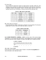
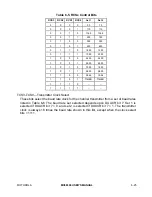
Table 6-4. SBx Control Bits
SB3
SB2
SB1
SB0
Length 6-8 Bits
Length 5 Bits
0
0
0
0
0.563
1.063
0
0
0
1
0.625
1.125
0
0
1
0
0.688
1.188
0
0
1
1
0.750
1.250
0
1
0
0
0.813
1.313
0
1
0
1
0.875
1.375
0
1
1
0
0.938
1.438
0
1
1
1
1.000
1.500
1
0
0
0
1.563
1.563
1
0
0
1
1.625
1.625
1
0
1
0
1.688
1.688
1
0
1
1
1.750
1.750
1
1
0
0
1.813
1.813
1
1
0
1
1.875
1.875
1
1
1
0
1.938
1.938
1
1
1
1
2.000
2.000
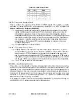
6.4.1.3 STATUS REGISTER (DUSR). The DUSR indicates the status of the characters in
the FIFO and the status of the channel transmitter and receiver.
DUSRA, DUSRB
7
6
5
4
3
2
1
0
RB
FE
PE
OE
TxEMP
TxRDY
FFULL
RxRDY
RESET:
0
0
0
0
0
0
0
0
Read Only
RB—Received Break
1 = An all-zero character of the programmed length has been received without a stop
bit. The RB bit is only valid when the RxRDY bit is set. Only a single FIFO
position is occupied when a break is received. Further entries to the FIFO are
inhibited until the channel RxDx returns to the high state for at least one-half bit
time, which is equal to two successive edges of the internal or external 1
×
clock
or 16 successive edges of the external 16
×
clock.
The received break circuit detects breaks that originate in the middle of a
received character. However, if a break begins in the middle of a character, it
must persist until the end of the next detected character time.
0 = No break has been received.