


MOTOROLA
MC68306 USER'S MANUAL
6-3
6.1.1 Serial Communication Channels A and B
Each communication channel provides a full-duplex asynchronous/synchronous receiver
and transmitter using an operating frequency independently selected from a baud rate
generator or an external clock input.
The transmitter accepts parallel data from the bus, converts it to a serial bit stream, inserts
the appropriate start, stop, and optional parity bits, then outputs a composite serial data
stream on the channel transmitter serial data output (TxDx). Refer to 6.3.2.1 Transmitter
for additional information.
The receiver accepts serial data on the channel receiver serial data input (RxDx), converts
it to parallel format, checks for a start bit, stop bit, parity (if any), or break condition, and
transfers the assembled character onto the bus during read operations. Refer to 6.3.2.2
Receiver for additional information.
6.1.2 Baud Rate Generator Logic
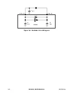
The crystal oscillator operates directly from a 3.6864-MHz crystal connected across the
X1/CLK input and the X2 output or from an external clock of the same frequency
connected to X1/CLK. The clock serves as the basic timing reference for the baud rate
generator and other internal circuits.
The baud rate generator operates from the oscillator or external CMOS clock input and is
capable of generating 18 commonly used data communication baud rates ranging from 50
to 38.4k by producing internal clock outputs at 16 times the actual baud rate. Refer to 6.2
Serial Module Signal Definitions and 6.3.1 Baud Rate Generator for additional
information.
6.1.3 Timer/Counter
The timer/counter provides for an input which bypasses the baud rate generator, and
provides a synchronous clock mode of operation when used as a divide-by-1 clock and an
asynchronous clock mode when used as a divide-by-16 clock. The external clock input
allows the user to use the external input as the only clock source for the serial module if
multiple baud rates are not required.
6.1.4 Interrupt Control Logic
Two interrupt request signals (
IRQ
and
TIRQ
) are provided to notify the CPU of an
interrupt condition. The
IRQ
output is the logical NOR of all (up to eight) unmasked
interrupt status bits in the interrupt status register (DUISR). The
TIRQ
output is the
inverted counter/timer ready interrupt status.
TIRQ
can be masked by the IENT bit of the
interrupt control register external to the serial module.
The interrupt level of the serial module
IRQ
is programmed in the system register external
to the serial module. When an interrupt at this level is acknowledged, the serial module is
serviced before the external IRQ7 of the same level.