


6- 4
MC68306 USER'S MANUAL
MOTOROLA
The
TIRQ
interrupt (if enabled) is fixed at level seven. When a level seven interrupt is
acknowledged, the
TIRQ
interrupt is serviced before the external IRQ7. If the serial
module
IRQ
is also programmed at level seven, the
TIRQ
interrupt is serviced first, then
the serial module
IRQ,
then the external IRQ7 last.
If the
TIRQ
interrupt is enabled, the serial module counter/timer ready interrupt in the
DUISR should be masked, and the
IRQ
service routine should not service the
counter/timer ready condition.
6.1.5 Comparison of Serial Module to MC68681
The serial module is code compatible with the MC68681 with some modifications, but
OP2, OP4–7, and IP3–5 are not pinned out. A new interrrupt output (
TIRQ)
is available.
6.2 SERIAL MODULE SIGNAL DEFINITIONS
The following paragraphs contain a brief description of the serial module signals. Figure 6-
2 shows both the external and internal signal groups.
NOTE
The terms
assertion and negation are used throughout this
section to avoid confusion when dealing with a mixture of
active-low and active-high signals. The term
assert or assertion
indicates that a signal is active or true, independent of the level
represented by a high or low voltage. The term
negate or
negation indicates that a signal is inactive or false.
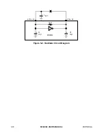
6.2.1 Crystal Input or External Clock (X1/CLK)
This input is one of two connections to a crystal or a single connection to an external
clock. A crystal or an external clock signal, at 3.6864 MHz, must be supplied when using
the baud rate generator. If a crystal is used, a capacitor of approximately 10 pF should be
connected from this signal to ground. If this input is not used, it must be connected to V
CC
or GND.
6.2.2 Crystal Output (X2)
This output is the additional connection to a crystal. If a crystal is used, a capacitor of
approximately 5 pF should be connected from this signal to ground. If an external CMOS-
level clock is used on X1/CLK, the X2 output must be left open.
6.2.3 Channel A Transmitter Serial Data Output (TxDA)
This signal is the transmitter serial data output for channel A. The output is held high
('mark' condition) when the transmitter is disabled, idle, or operating in the local loopback
mode. Data is shifted out on this signal on the falling edge of the clock source, with the
least significant bit transmitted first.