


Troubleshooting
5-26 Manual # 42-02-2P24
MPI A or B LANDING SYSTEM COMM LOSS
Description:
The TC-MPI board is not communicating with the landing system properly (A or B channel
lost). The TC-MPI board and the ELGO landing system have dedicated 120-ohm resistors across the high
and low channels of both CAN1 and CAN2. When the TC-MPI and the ELGO landing system are connected
together, the resistance across CANH1 to CANL1 should read about 60-ohms. The same is true for CANH2
to CANL2. CAN2 is also shared with any HC-UIO, MC-CPI or ICE-COP-2 plugged into the MC-LSI board. The
boards also have termination resistors which can affect the load on CAN2. On the HC-UIO, make sure the
JP2 jumper immediately to the right of the internal network connection is NOT terminated. On any MC-CPI
or ICE-COP-2 board, make sure the JP1 jumper in the lower right hand corner is NOT terminated.
Troubleshooting
:
1. On the controller HC-MPU board, place F3 in the UP position. Press “N” to access the system menu.
Press “N” to advance to the Controller System Menu. Press “S” to select. Press “N” until ELGO A and
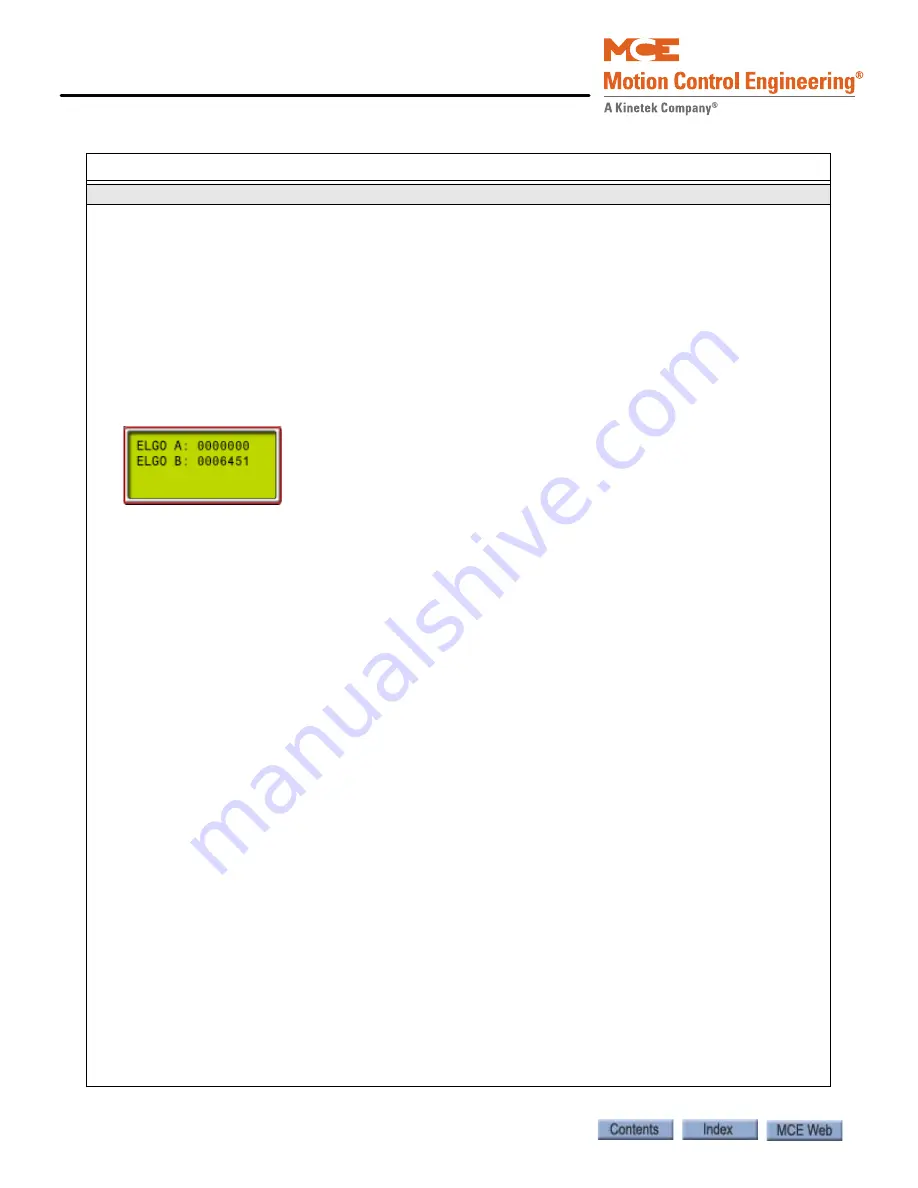
ELGO B is displayed.If a channel has failed, the position information for that channel will be missing.
ELGO A uses CAN 2, along with the cartop HC-UIO, MC-CPI, and ICE-COP-2 boards. For example:
Connections Through Traveler
1. Check that the CAN connections at J17 on the TC-MPI board are clean and tight.
2. On the cartop, temporarily disconnect the MACHINE ROOM / CANL2 and CANH2 wires from the MC-LSI
board. Measure the resistance between them. (All resistance measurements must be performed with
power off.) It should read about 120-ohms. Repeat for the CANL1 and CANH1 wires. They should also
read about 120-ohms.
3. With power off and all CAN connections to the cartop terminated, resistance should be close to 60-
ohms.
If a measured resistance is other than shown, you may have a damaged, broken, or shorted wire in the
traveler. Resolve this issue before proceeding with additional troubleshooting.
CHANNEL A
1. If the lost channel is the A (CAN 2) channel, verify cartop mounted UIO board baud rate selection is
correct, 5-60. Next, unplug all HC-CPI (control panel interface) and HC-UIO (universal I/O) board CAN
connections from the MC-LSI (landing system interface board) on the cartop (CAN 2 is a shared
bus).Recheck the display to see if both channels are now back on line.
2. If the ELGO channels are now OK, reconnect the UIO boards one at a time. If the channel is lost, check
the CAN terminations on the UIO board. If the board is terminated, open the termination by moving
the jumper so the header pins are not shorted. Repeat for additional UIO boards, checking ELGO infor-
mation as you go.
3. Check the car panel interface boards to see that only the last board in the string is terminated (CAN).
Reconnect the CPI boards. Check ELGO information. If the A channel is lost again as you reconnect
boards, contact MCE support for help in isolating the bad board or termination.
4. If, after disconnecting the CPI and UIO boards, the A channel remained off line, temporarily connect
CAN 1 connections to CAN 2 on the TC-MPI board. Place the processor F3 switch down and check the
error code on the display:
• MPI-A INCORRECT LANDING SYSTEM CONNECTED - replace the ELGO reader head
• MPI-A LANDING SYSTEM COMM LOSS - continue numbered steps.
5. Temporarily connect CAN 2 connections to CAN 1 on the TC-MPI board. If the message changes to MPI-
A INCORRECT LANDING SYSTEM CONNECTED, replace the ELGO reader head. If the message remains
MPI-A LANDING SYSTEM COMM LOSS, replace the TC-MPI board.
CHANNEL B
1. If the lost channel is the B (CAN 1) channel, temporarily connect CAN 2 to CAN 1 on the TC-MPI board.
2. If the display changes to MPI-B INCORRECT LANDING SYSTEM CONNECTED, replace the TC-MPI board.
3. If the message remains MPI-B LANDING SYSTEM COMM LOSS, replace the ELGO reader head.
Table 5.1 Status and Error Messages
Scrolling Message - Special Event Message
Содержание Motion 4000
Страница 20: ...xiv Manual 42 02 2P24 5 20 13 ...
Страница 38: ...Motion 4000 Traction Elevator Control 1 18 Manual 42 02 2P24 ...
Страница 178: ...Final Adjustments 3 56 Manual 42 02 2P24 ...
Страница 322: ...User Interface 4 144 Manual 42 02 2P24 ...
Страница 391: ...PC Board Quick References 5 69 5 Motion 4000 Figure 5 11 Example MC CPI Wiring ...
Страница 439: ...Customer Notations A 27 A Motion 4000 Customer Notations Table A 4 Customer Notation Area ...
Страница 444: ...Appendix A 32 Manual 42 02 2P24 ...


