01/12/17 M34 (TS)_EN
ENGLISH
ENGLISH
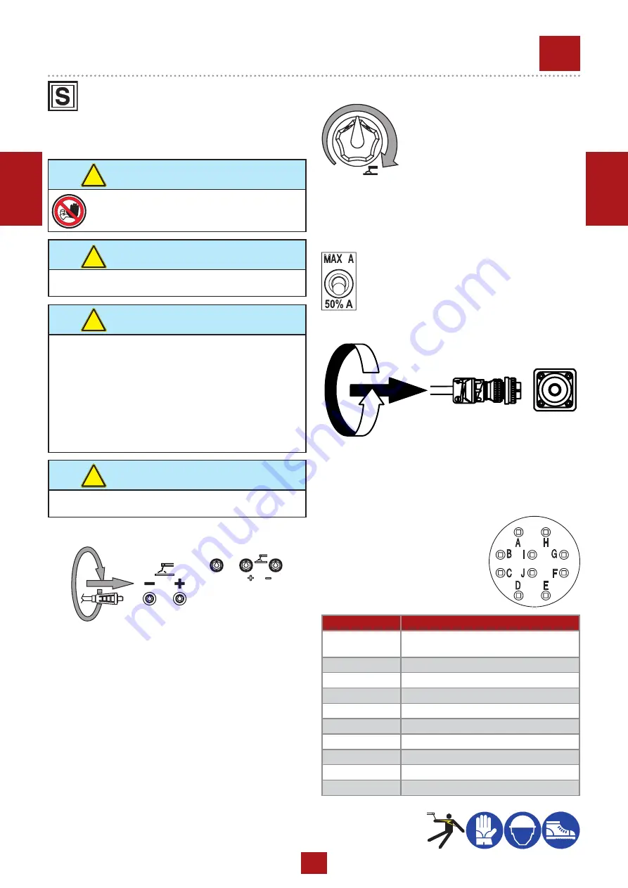
ADJUSTING THE WELDING CURRENT
The welding current is regulated by tur-
ning knob “T” continuously. If set to the
minimum (turned fully in an anticlockwise
direction) it provides a current of approxi-
mately 20 A; if set to the maximum (turned
fully in a clockwise direction) it gives a
maximum current of approximately 600A
(20V). Position welding current adjusting knob (T) in corre-
spondance of the chasen current value, so as to obtain the
necessary amperage, taking into acount the diameter and the
type of the electrode. For technical data see page M1.6
REDUCTION SCALE SWITCH
For small electrodes (up to Ø 4-200A) it is recommen-
ded to use the reduction scale switch (I3) allowing a
more accurate regulation of the welding current (lever
position at 50%).
M
34
USE AS WELDER
This symbol (Norm EN 60974-1 security standards for
arc welders ) signifies that the welder can be used in
areas with increased risk of electrical shock.
CONNECT WELDING CABLES
Assure the right ground connection (12) (when and if needed).
For this purpose see chapter “GROUND CONNECTION”.
WARNING
It is prohibited for any unauthorized persons to
access areas adjacent to the engine driven welder
or the welding process.
!
WARNING
The sockets, after the machine is started, also with no cables,
are anyway under voltage.
!
WARNING
To reduce the risk of electromagnetic interferences, use the
minimum lenght of welding cables and keep them near and
down (ex. on the floor).
The welding operations must take place far from any sensitive
electronic device.Make sure that the unit is earthed. (see M20
and/or M25). In case the interference should last, adapt further
disposition,such as: move the unit, use screened cables, line
filters, screen the entire work area.
In case the above mentioned operations are non sufficient,
please contact our Technical Assistance Service.
!
CAUTION
With a
welding cable length up to 10 m is suggested a section
of 35 mm²; wìth longer cables a bigger section is required.
!
Fully insert the welding cable plugs into the corresponding
sockets (“only gauging”, 9
+
/10
-
) turnning them clockwise to
lock them in position. Make sure that the ground clamp ,whose
cable must be connected to the + or - terminal, depending on
the type of electrode, makes a good connection and is near to
the welding position. Pay attention to the two polarities of the
welding circuit, which must not come in electric contact between
themselves.
Carefully tighten the output cables to the bushings; if loose,
they can cause problems of overheating and damage the
bushings, cables, etc.
When using the welder for air arc gouging connect the ground
lead to the - socket and the gouging lead to the socket marked
"only gouging
"
(if present).
ONLY GOUGING
PUSH AND
TWIST
PUSH AND
TWIST
The welding machine is predisposed for connection to a re-
mote control (optional) by means of the circular connector lo-
cated on the front panel. Once the connection to the remote
control has been made, the function of regulating the main
potentiometer, located on the front panel, will be automatically
switched to the remote control potentiometer.
REMOTE CONTROL
CONTACTS
DESCRIPTIONS
A
(electric ground)
To the RC1 potentiometer - GND terminal
B
To the RC1 potentiometer - V
CONTR
terminal
C
To the RC1 potentiometer - V
REF
terminal
D
Non connected
E
Polarity switch version
F
Polarity switch version
G
Non connected
H
Non connected
I
Non connected
J
Non connected
The following table describes
the functions of each of the
connector’s contacts.
REV
.1-05/19
Содержание TS 400 YS
Страница 2: ......
Страница 40: ...11 01 01 Note NOTE 46...
Страница 41: ...11 01 01 Note NOTE 46...
Страница 42: ...11 01 01 Note NOTE 46...
Страница 43: ......


