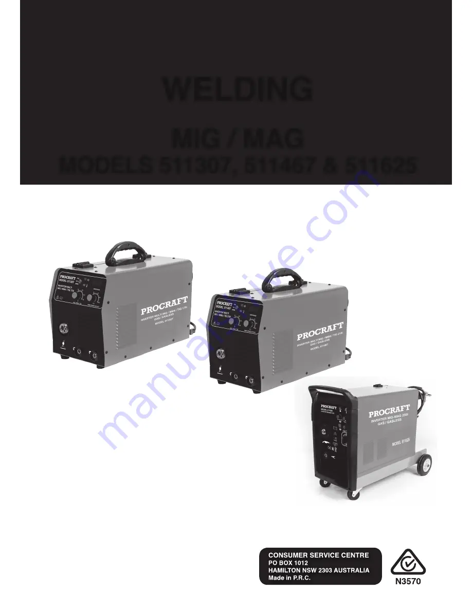
background image

MIG / MAG

MODELS 511307, 511467 & 511625

WELDING

SAVE THIS MANUAL

WARNING!

READ AND UNDERSTAND ALL INSTRUCTIONS

Failure to follow all instructions listed below may result 

in electric shock, fire, and/or serious injury.
SAVE THESE INSTRUCTIONS
Keep this manual for the safety warnings and precautions, 

assembly, operating, inspection, maintenance and 

cleaning procedures. Write the product’s serial number 

in the back of the manual (or month and year of purchase 

if product has no number). Keep this manual and the 

receipt in a safe and dry place for future reference.

OPERATING INSTRUCTIONS

PROCRAFT

Содержание 511307

Страница 1: ...d or serious injury SAVE THESE INSTRUCTIONS Keep this manual for the safety warnings and precautions assembly operating inspection maintenance and cleaning procedures Write the product s serial number in the back of the manual or month and year of purchase if product has no number Keep this manual and the receipt in a safe and dry place for future reference OPERATING INSTRUCTIONS PROCRAFT ...

Страница 2: ...Page 2 FIG 1 511307 170i Multi MIG MMA TIG FIG 2 511467 210i Multi MIG MMA TIG ...

Страница 3: ...Page 3 FIG 1 511625 250i MIG MAG ...

Страница 4: ... the safety alert symbol indicates a hazardous situation which if not avoided could result in minor or moderate injury NOTICE NOTICE is used to address practices not related to personal injury SAFETY WARNINGS AND PRECAUTIONS WARNING When using tool basic safety precautions should always be followed to reduce the risk of personal injury and damage to equipment Read all instructions before using thi...

Страница 5: ... Power Cord to carry the tool or pull the Plug from an outlet Keep the Power Cord away from heat oil sharp edges or moving parts Replace damaged Power Cords immediately Damaged Power Cords increase the risk of electric shock 6 When operating a power tool outside sue an outdoor extension cord marker W A or W These extension cords are rated for outdoor use and reduce the risk of electric shock Perso...

Страница 6: ...k for misalignment or binding of moving parts breakage of parts and any other condition that may affect the tool s operation If damaged have the tool serviced before using Many accidents are caused by poorly maintained tools 8 Use only accessories that are recommended by the manufacturer for your model Accessories that may be suitable for one tool may become hazardous when used on another tool Ser...

Страница 7: ...es wear flame resistant ear plugs or ear muffs to keep sparks out of ears 8 Prevent accidental fires Remove any combustible material from the work area a When possible move the work to a location well away from combustible protect the combustibles with a cover made of fire resistant material b Remove or make safe all combustible materials for a radius of 35 feet 10 meters around the work area Use ...

Страница 8: ... Limits PEL s for various fumes and gases Follow the American Conference of Governmental Industrial Hygienists recommendations for Threshold Limit Values TLV s for fumes and gases Have a recognized specialist in Industrial Hygiene or Environmental Services check the operation and air quality and make recommendations for the specific welding or cutting situation 10 Always keep hoses away from weldi...

Страница 9: ...tter Using components from other systems may cause personal injury and damage components within 15 People with pacemakers should consult their physician s before using this product Electromagnetic fields in close proximity to a heart pacemaker could cause interference to or failure of the pacemaker 16 USE PROPER EXTENSION CORD Make sure your extension cord is in good condition When using an extens...

Страница 10: ... 2 18 0 10 Welding current MMA 10 170 20 180 Welding current MIG 40 170 40 200 40 250 No load voltage V 65V 65V 39V Duty cycle 120A 100 170A 30 140A 100 170A 60 160A 100 200A 60 Wire diameter mm Ф0 6 0 8 0 9 Ф0 6 0 8 0 9 1 2 Ф0 6 0 8 0 9 1 2 Welding thickness mm 0 6 4 0 0 6 6 0 0 8 10 0 Cover protection IP21S IP21S IP21S Insulation F F F Dimension L W H mm 520 x 330 x 360 520 x 335 x 365 870 x 390...

Страница 11: ...work table must allow the work metal to be firmly clamped to prevent it accidentally falling or moving 3 The floor and surrounding area of your work site must not be flammable A clean cement floor is recommended The cutting process will eject molten metal slag onto the floor and it will scatter for 8 10 feet or more in any direction Have an adequate fire extinguisher available if needed ASSEMBLY A...

Страница 12: ...se connect the TIG torch control cable in to TIG control socket 8 and connect the earth cable to the socket 2 Working Indicator Light It will be on during welding operation 3 Thermal Overload Indicator Lamp This light will come on and the device will shut down if the tool becomes overheated Stop trying to use the cutter while leaving the power switch onto allow the cooling fan to operate and the l...

Страница 13: ... length of spot weld time 12 Soft Start controls the voltage supply when the weld is starting TIG Torch Connect MMA welding MIG welding connect Setting the Gun polarity For Wire type 1 Set for Electrode Positive GAS for gas welding with solid core wire and the gas supply is needed Note When it is gas welding you also should set common Wire feed rolls 2 Set for Electrode Negative DCEN for gasless f...

Страница 14: ...ile you cut enough Wire off the end of the Spool to remove all bent and crimped Wire Make sure the cut end has no burrs or sharp edges cut again if needed 3 Loosen and lower the Tension Adjusting Knob 1a on the Wire Feed Assembly Then raise the Swing Arm 2a 4 Keep tension on the Welding Wire and guide at least 12 inches of Wire into the Wire Feed Leader 3a 5 Lower the Swing Arm 2a on the Wire Feed...

Страница 15: ...d tips inside the tip of the MIG Torch handle Insert the Contact Tip 2b onto the Welding Wire and screw it firmly into the Head Tube 3b of the Torch Handle Replace the Nozzle 1b and cut off any excess Welding Wire over 1 2 inches 9 Connect a hose and coupling from the gas regulator on a CO2 gas tank none included to the CO2 Gas Inlet on the back of the unit Follow the gas cylinder manufacturer s i...

Страница 16: ...do not contact it 5 Stroke the work piece lightly to ignite the arc Do not strike like a match Never tap the electrode wire to ignite the arc it will damage the electrode 6 When the arc ignites tilt the electrode forward and hold it near the work piece Arc stick Welding 1 Turn the Current Adjustment Knob to meet the needs of the job 2 Move the Stick or TIG Switch to TIG 3 Connect the Electrode Cla...

Страница 17: ...ect welding technique Place stringer bead at correct place in joint Adjust work piece position or weld angle to permit proper welding at bottom of work piece Pause briefly at sides when using a weave bead Keep arc on leading edge of weld puddle Hold gun at proper angles and make tack welds to help hold pieces Possible causes and Solutions 1 Work pieces too thick close Joint design must allow weld ...

Страница 18: ...n chipped melted cracked or otherwise damaged the nozzle will adversely effect the weld and should be replaced 4 Reinstall the Nozzle 1a after inspecting and cleaning the Contact Tip Contact tip Inspection cleaning and replacement 1 Make sure the entire Welding torch is completely cool before proceeding 2 Remove the nozzle as explained above Then remove the contact tip 3 Scrub the exterior of the ...

Страница 19: ...h the power cable and transmits the electrical energy to the electrode while directing it to the weld area It must be firmly secured and properly sized since it must allow the passage of the electrode while maintaining an electrical contact Before arriving at the contact tip the wire is protected and guided by the electrode conduit and liner which help prevent buckling and maintain an uninterrupte...

Страница 20: ...pular a negatively charged electrode is rarely employed Technique The basic technique for GMAW is quite simple since the electrode is fed automatically through the torch By contrast in gas tungsten arc welding the welder must handle a welding torch in one hand and a separate filler wire in the other and in shielded metal arc welding the operator must frequently chip off slag and change welding ele...

Страница 21: ...ure Adjust wire feed pressure properly follow instructions on page 11 12 2 Incorrect contact tip size Replace with the proper tip for the wire size used 3 Gun end not inserted into drive housing properly Loosen gun securing bolt and push gun end into housing just enough so that it does not touch wire feed mechanism 4 Damaged liner Have a qualified technician inspect and repair replace as necessary...

Страница 22: ...rnal fuse blown Have a qualified technician check replace Weak arc strength Possible causes and solutions 1 Incorrect line voltage Check the line voltage and if insufficient have a licensed electrician remedy the situation Wire Feeds but arc does not ignite Possible causes and solutions 1 Improper ground connection Make certain that the work piece is contacted properly by the Ground Clamp and that...

Страница 23: ...eds but shielding gas does not Flow Possible causes and solutions 1 Empty Gas cylinder Check gas cylinder 2 Nozzle plugged Clean nozzle If damaged replace 3 Regulator or cylinder valve closed Make sure both valves are adjusted properly 4 Gas line blocked Check external hose and hose within Torch cable 5 Gas solenoid broken or not connected properly Have a qualified technician check replace ...

Страница 24: ... MIG MMA TIG INCLUDED STANDARD ACCESSORIES 4m Cable Electrode Holder 500890 4m Cable Earth Clamp 500892 SB15 4m Long MIG Torch 500886 Argon Regulator INCLUDED STANDARD ACCESSORIES 4m Cable Electrode Holder 500891 4m Cable Earth Clamp 500893 SB24 4m Long MIG Torch 511520 Argon Regulator ...

Страница 25: ...Page 25 511625 250i MIG MAG INCLUDED STANDARD ACCESSORIES INCLUDED STANDARD ACCESSORIES SB24 4m Long MIG Torch 511520 Argon Regulator 4m Cable Earth Clamp 500893 ...

Отзывы: