background image

www.miinet.com

Moore Industries-International, Inc.

- 58 -       

User’s Manual

238-760-00K

May 2019

Functional Safety Dual Input Smart HART® Temperature Transmitter 

STZ

SECTION 4

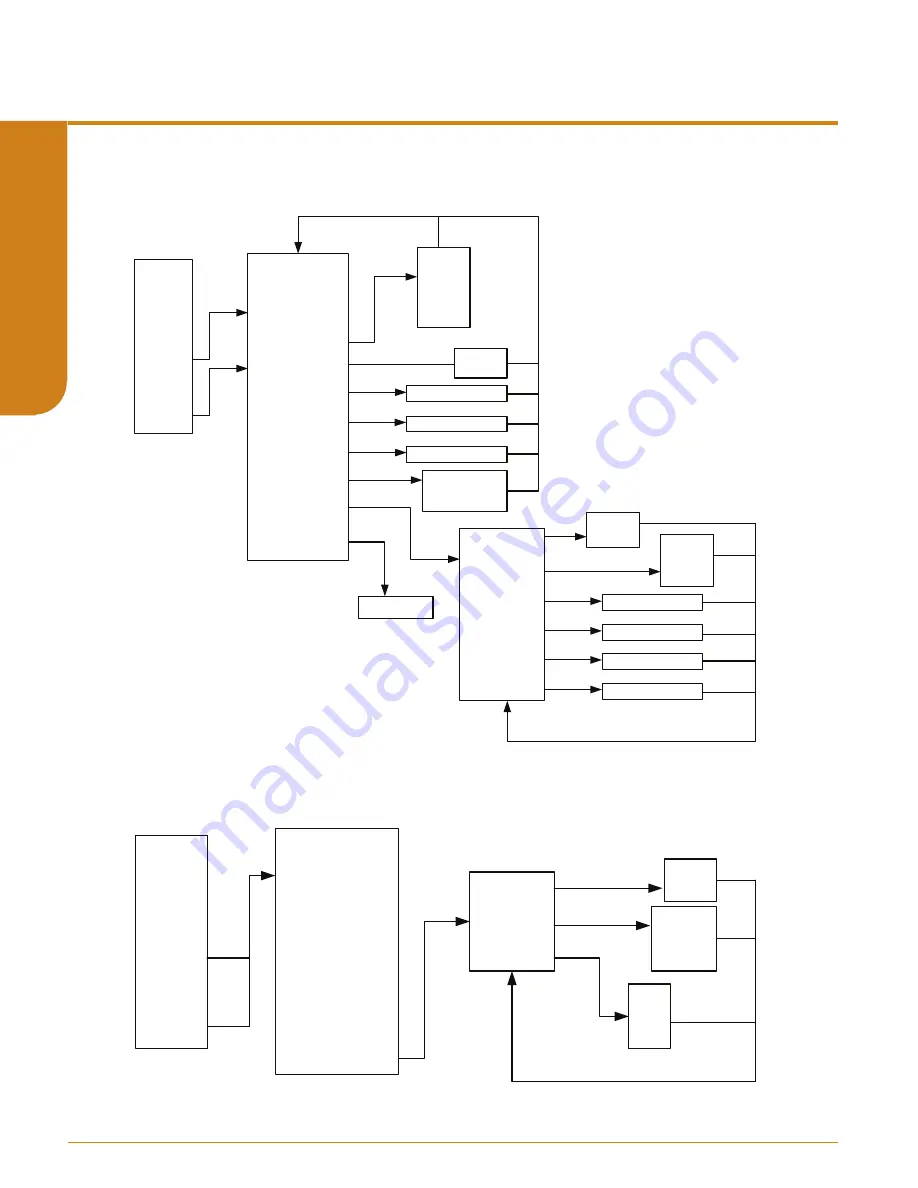
Figure 4.6.

  STZ


Sensor 1 and Sensor 2 menus in Input menu  

Configure 

Input Types

RJC Temp


Sensor 1

Sensor 2

SX Measure Mode

S1 Input Type

Sensor 1 EGU

SX Broken Wire Detecon

SX BW Holdoff Time

SX Running Average

SX 2Wire Offset

SX Sensor Informaon

SX Scaling

SX Custom Curve*

Sensor X USL

Sensor X LSL

Sensor X Min Span

Sensor X s/n

degC

degF

degR

Kelvin

mV

ohm

%

Disabled

Enabled

Enter Holdoff Time

Enter SX Running Average

Enter SX 2Wire Offset

Sensor X Scl En

Sensor X EGU

Sensor X Input Min.

Sensor X Input Max.

Sensor X Scale Min.

Sensor X Scale Max.

Disabled

Enabled

inH2O

inHg

H2O

…..

Enter Sensor X Input Min.

Enter Sensor X Input Max.

Enter Sensor X Scale Min.

Enter Sensor X Scale Max.

See Figure 4.7

Figure 4.7.

  STZ Custom Curve for Sensor 1 and Sensor 2 in Input menu  

Configure 

Input Types

RJC Temp


Sensor 1

Sensor 2

SX Measure Mode

S1 Input Type

Sensor 1 EGU

SX Broken Wire Detecon

SX BW Holdoff Time

SX Running Average

SX 2Wire Offset

SX Sensor Informaon

SX Scaling

SX Custom Curve*

Sensor X CC En

Sensor X EGU

Sensor X CC ID

Disabled

Enabled

inH2O

inHg

H2O

…..

CC 1

CC 2

CC 3

CC 4

Содержание STZ

Страница 1: ...STZ No 238 760 00K May 2019 Functional Safety Dual Input Smart HART Temperature Transmitter ...

Страница 2: ...orth Hills California 91343 6196 U S A Tel 818 894 7111 Fax 818 891 2816 E mail info miinet com TOLL FREE 1 800 999 2900 www miinet com China Room 102 No 101 Lane 1058 Xinzhen Street Xinqiao Town Songjiang District Shanghai 201612 P R China Tel 86 21 62491499 Fax 86 21 62490635 E mail sales mooreind sh cn www miinet com cn Europe 1 Lloyds Court Manor Royal Crawley W Sussex RH10 9QU United Kingdom ...

Страница 3: ... procedure or condition that could injure the operator Qualified Personnel The Moore Industries product systems described in this manual may be operated only by personnel qualified for the specific task in accordance with the relevant documentation in particular its warning notices and safety instructions Qualified personnel are those who based on their training and experience are capable of ident...

Страница 4: ... Check 26 Section 3 Installation and Wiring 28 Terminal Designations 28 Dimensions 29 Installation in Hazardous Locations 34 Specific Conditions of Use 34 Section 4 Configuration 40 Programming Device Description Menu on STZ with HART Communicator hand held devices 47 DD Device Setup Reference Guide 49 Section 5 Configuration using FDT DTM Software 72 STZ DTM Parameter in Basic Setup Configuration...

Страница 5: ...ture Transmitter STZ Table of Contents Section 8 Applications 124 Point to Point Loops with Remote Programmability 124 Using HART monitoring for Additional Diagnostic Data 126 SIL 3 Application Example 127 Section 9 Specifications 128 Section 10 Ordering Information 131 Section 11 Certification Information 133 Warranty Disclaimer 146 ...

Страница 6: ...al designation table located in this manual If you are using the STZ in a safety instrumented system then you must read and follow the safety section 7 in this user manual Default Configuration Single Sensor Mode Sensor 1 4Wire RTD Pt3850 100Ohms 0 100deg C Broken Wire Enabled Sensor 2 Disabled 0 seconds Filter 60Hz Running Average Filter Disabled Setting 1 PV Damping Disabled 0 seconds Display So...

Страница 7: ...ter will drive the analog output upscale downscale preset value or will hold last output The STZ has enhanced device intelligence which includes sensor drift corrosion detection range alarms and device diagnostics These can check and alert the user when thermocouples fail unexpectedly resistance thermometers exceed set parameters or the device has failures A more detailed explanation of these feat...

Страница 8: ... specify the specific sensor in a temperature transmitter assembly see RTI series data sheets for more information If a second sensor is required in the assembly then this needs to be ordered separately Note While the STZ will accept a dual input sensor configuration the following limitations apply only when using two input sensors STZ HP 2 wire and or 3 wire sensors 4 wire sensors RTDs cannot be ...

Страница 9: ...its with this option have blue input terminals HOUSING HP STZ with display is available in an HP housing The HP unit can also be ordered in an explosion proof or protective enclosure e g BH SB etc or with a clip for DIN rail or track mounting HPP Encapsulated hockey puck housing for mounting in connection heads The HPP unit can also be ordered in an explosion proof enclosure e g LH2 DIN DIN style ...

Страница 10: ...Sensor 2 For both single sensor and two sensor inputs there are many other variables known as Device Variables that are calculated from the inputs Most HART commands use variables known as Dynamic Variables The Device Variables need to be assigned or mapped to the Dynamic Variables The tables below define the Device Variables and Dynamic Variables Table 1 1 Device Variables Device Variable Descrip...

Страница 11: ...rst mode the STZ will proactively send out messages instead of waiting for the host to request them This enables event driven communication high low deviation of signal or change in status and or timed communication every 20 seconds to the host Up to 3 different burst messages may be configured in the STZ Please see section 4 for more information on burst mode configuration Note When using burst m...

Страница 12: ...ments 4 independently configurable Range Alarms Typical applications are outside of range detection in range detection and sensor drift Range Alarms RA can be used to detect if a Device Variable is inside or outside of an arbitrary user specified range Any Device Variable can be used as the source including the RJC Temperature Loop Current and Percent of Range POR The alarm can be set to a warning...

Страница 13: ...t the same point This method can provide a range alarm warning or alarm to indicate that there is an issue with one of the sensors See Chart below for clarification In this example a Range Alarm is set with the Absolute Differential as the source An out of range warning or alarm is configured with the low and high limits set to 0C to 5C respectively creating an alarm when Sensor 1 and Sensor 2 rea...

Страница 14: ... additional time delay before the broken wire diagnostic alert is reported When enabled a Broken Wire delay of 0 60 seconds can be set This feature prevents the transmitter from going into a fault state when intermittent high levels or spikes of extraneous plant noise is conducted onto the sensor leads To setup Corrosion Detection the user captures the nominal sensor resistance value and sets the ...

Страница 15: ...THERMOCOUPLE mV TB1 TB2 TB3 TB4 TB5 2W RTD Resistance THERMOCOUPLE mV TB1 TB2 TB3 TB4 TB1 TB2 TB3 TB4 TB5 THERMOCOUPLE mV Sensor 1 Sensor 1 Sensor 2 Sensor 2 TB1 TB2 TB3 TB4 TB5 3W RTD Resistance P S P S PS PS STZ HPP STZ DIN STZ HP TB1 TB2 TB3 TB4 TB5 TB2 TB3 T B 4 T B 1 PS PS TB1 TB2 TB3 TB4 TB5 STZ HPP 4 Terminals Input Connections STZ HP and STZ DIN 5 Terminals Input Connections Note STZ HPP s...

Страница 16: ... analog output Sensor trimming increases the measurement accuracy of your instrument by matching the reading of its actual input to its scaling The STZ offers the use of a trimming feature that can be accessed using a HART Communicator a HART Host or an FDT Host such as PACTware Likewise output trimming increases the measurement accuracy of the STZ by calibrating its analog output to the device th...

Страница 17: ...e Mode is RTD 4 wire and the Sensor 1 Input Type is Pt 3850 1000 ohm and Sensor 1 EGU is deg F then you should be using an accurate resistance source such as a decade box to emulate the 4 wire Pt 3850 1000Ω RTD and use the Fahrenheit temperature tables to source the correct resistances for your specific temperature range Be sure to also check the HART Communicator s Online Menu to see your instrum...

Страница 18: ...ur instrument to loop control and verify that your input is reading correctly 12 You can then perform the Variable Trim for Sensor 2 if you are using a dual sensor configuration Trimming for a thermocouple input will be similar except you will be providing an accurate millivolt signal to simulate temperature To perform the Output Trimming of the STZ set up the equipment specified in Table 2 1 then...

Страница 19: ...ss the 250Ω resistor A 4mA output will read as 1V across the resistor 7 Follow the instructions on the screen of your HART Communicator and then proceed to Trim Full 8 Use your voltmeter to measure the voltage drop across the 250Ω resistor A 20mA output will read as 5V across the resistor Figure 2 6 Output Trimming with HART Communicator Online Menu Model Device Setup PV is PV Quality PV PV Loop C...

Страница 20: ...0 250 ohms with 0 01 precision Calibrated to an accuracy of 0 025 or better such as Fluke Model 725 or similar Device Specifications Millivolt or Resistance Source Power Supply Load Resistor Multimeter PACTware version 4 1 SP3 or newer PC with PACTware or FDT frame application Moore Industries P N 803 040 26 or 804 030 26 Communications Cable For instructions on installation and setup of the STZ D...

Страница 21: ...eck the Configure Sensors settings in PACTware This will help you to be sure to apply the correct input with which to trim your STZ By example If the Sensor 1 Input is 3W RTD and the Type is Pt3850 1000 and Engineering Units is degrees Celsius then you should be using an accurate resistance source such as a decade box to emulate the 3 wire Pt 3850 1000Ω RTD and use the Celsius temperature tables t...

Страница 22: ...k the Ranging and Mapping settings in PACTware In Figure 2 9 you can see that Sensor 1 is mapped to the Primary Variable and the range is defined as 0 100 Degrees C Now you are ready to do the actual input trimming of your STZ Proceed to Sensor 1 Trim in PACTware as seen in Figure 2 10 Functional Safety Dual Input Smart HART Temperature Transmitter STZ SECTION 2 ...

Страница 23: ...o Two Point 2 Set your input resistance to match your Sensor 1 Zero point By example If your Sensor 1 Zero point is 0 C the input you apply to the instrument will be 1000 00Ω 3 Enter the Sensor 1 Zero value into the field entitled Desired Trim Point Value For my example I will be entering 0 as my range is defined as 0 100 4 When your reading stabilizes press the Trim Lower Point button and your Se...

Страница 24: ...ur DCS is reading 11 85mA you can trim the output of the STZ so that the two readings will match Note trimming of the analog output will not affect the HART digital data To perform output trimming set up your STZ as shown in Figure 2 11 ADDR ADDR AD STZ 12 24Vdc Power Supply Voltmeter Load 250 ohm Moore Industries P N 804 030 26 To USB Port of PC PC HART Modem connects to Serial USB COM Port of PC...

Страница 25: ...2mA 1 08V 250Ω 4 32mA Enter this value in the Measured Output Current box and then push the Trim button Now select the Upper Output Range This will set the instrument s output to 20mA Use your voltmeter to read the voltage drop across the 250Ω resistor and calculate the actual current going through the resistor Example A voltage reading of 4 91v equates to 19 64mA 4 91V 250Ω 19 64mA Enter this val...

Страница 26: ...bient temperature of 72 then you should expect an output of 11 04mA If it is not feasible for you to use the actual temperature sensor for your bench test or if your desired temperature range is nowhere near your ambient temperature then use a temperature simulator such as a Fluke 725 or similar to provide your input Once your bench setup is complete you can now use your FDT DTM software to check ...

Страница 27: ...me please refer to section 5 See Section 4 of this manual to configure your STZ as appropriate for your application If possible use the exact temperature sensor RTD or thermocouple that you will be using in your final application Apply power to the STZ and see that it is reading the correct ambient temperature and providing the correct output for the given input Example If your STZ is configured t...

Страница 28: ...e 3 1 Terminal Designations Terminal Designations TB1 TB2 TB3 TB4 2W RTD Resistance 3W RTD Resistance TB1 TB2 TB3 TB4 4W RTD Resistance TB1 TB2 TB3 TB4 POTENTIOMETER TB1 TB2 TB3 TB4 2W RTD Resistance TB1 TB2 TB3 TB4 POTENTIOMETER TB1 TB2 TB3 TB4 TB5 POTENTIOMETER TB1 TB2 TB3 TB4 TB5 4W RTD Resistance TB1 TB2 TB3 TB4 TB5 3W RTD Resistance TB1 TB2 TB3 TB4 TB5 2W RTD Resistance TB1 TB2 TB3 TB4 TB5 TH...

Страница 29: ...Dimensions Figure 3 2 Dimensions of STZ DIN Housing Figure 3 3 Dimensions of STZ HP Display Housing 62mm 2 45 in 75mm 2 97 in 63 5mm 2 50 in ADDR ADD ADDR R STZ Figure 3 4 Dimensions of STZ HPP Housing 32mm 1 27in 48mm 1 90in 33mm 1 30in 51mm 2 04in 23 4 40 Threas Inserts x 2 PLCS 51mm 2 04in 33mm 1 30in SECTION 3 5 31 in 135mm 4 04 in 102 6mm 1 11 in 28mm ...

Страница 30: ...ing PS PS 1 2 3 4 68mm 2 68 in GND 1 2 NPT 102mm 4 02 in 84mm 3 31 in 68mm 2 68 in 64mm 2 52 in 10mm 0 38 in 124mm 4 88 in 25mm 1 00 in 102mm 4 02 in 119mm 4 69 in 76mm 2 99 in 57mm 2 24 in 22mm 0 87 in SIDE VIEW TOP VIEW ADDR ADDR ADDR ADDR STZ Functional Safety Dual Input Smart HART Temperature Transmitter STZ SECTION 3 ...

Страница 31: ...itter STZ Figure 3 6 Dimensions of BH3 Housing 89mm 3 50 in 124mm 4 90in 70mm 2 75 in 57mm 2 25 in 31mm 1 25 in 62mm 2 45 in 89mm 3 50 in 44mm 1 75 in 25 4mm 1 0 in 6 6mm 26 in 70mm 2 75 in 57mm 2 25 in 76mm 2 99 in TOP VIEW BACK VIEW SIDE VIEW 65mm 2 56 in GND PS PS 1 2 3 4 ADDR ADDR ADDR ADDR STZ 101mm 4 0 in 115mm 4 55in 32mm 1 25 in SECTION 3 ...

Страница 32: ...trical Connections When installing any Moore Industries product always follow all local regulations and standards for grounding shielding and safety WARNING Terminals on this unit may be connected to hazardous voltages Before making ANY connections to this unit always remove power from the loop or instrument power terminals Installation Category All terminals are rated CAT I Equipment Ratings The ...

Страница 33: ...ing un wired Recommended Ground Wiring Practices Moore Industries recommends the following ground wiring practices Any Moore Industries product in a metal case or housing should be grounded The protective earth conductor must be connected to a system safety earth ground before making other connections All input signals to and output signals from Moore Industries products should be wired using a sh...

Страница 34: ... not allowed as it may impair the intrinsic safety AVERTISSEMENT La substitution de composants peut compromettre la sécurité intrinséque WARNING To prevent ignition of flammable or combustible atmospheres disconnect power before servicing AVERTISSEMENT Risque d explosion Avant de déconnecter l equipement couper le courant ou s assurer que débrancher tant que l emplacement est désigné non dangereux...

Страница 35: ...ications Class I Division 1 Groups A D Class1 Zone 0 AEx ia IIC Ex ia IIC The STZ shall be installed in an enclosure which maintains an ingress protection rating of at least IP20 and also meets the requirements of ANSI ISA 61010 1 or C22 2 No 1010 1 The COM port shall not be used in Hazardous areas Note Using the box provided on nameplate the User shall permanently mark type of protection chosen f...

Страница 36: ...external to the apparatus such that the voltage at the supply terminals of the STZ does not exceed 58 8V peak or 58 8Vdc The COM port shall not be used in Hazardous areas Note Using the box provided on nameplate the User shall permanently mark type of protection chosen for the specific installation Once the type of protection has been marked it shall not be changed Note Using the box provided on n...

Страница 37: ...Industries Fuse Protected USB Communications Cable Part No 804 030 26A as described on Control Drawing 100 100 80 or 100 100 81 The Cable cannot be used in Hazardous Areas or in ambient temperatures in excess of 75 C Note Using the box provided on nameplate the User shall permanently mark type of protection chosen for the specific installation Once the type of protection has been marked it shall n...

Страница 38: ...e NEC or the Canadian Electrical Code The enclosure shall at a minimum meet the requirements of IP20 When installed in Division 2 locations The STZ shall be mounted within a tool secured enclosure which meets the requirements of ANSI ISA 61010 1 or CAN CSA C22 2 No 61010 1 and is capable of accepting the applicable wiring methods wiring methods per the NEC or the Canadian Electrical Code When inst...

Страница 39: ...equipment shall only be cleaned with a damp cloth The STZ shall be provided with supply transient protection external to the apparatus such that the voltage at the supply terminals does not exceed 119Vac peak or 119Vdc IECEx Installations Ex ia Ga IIC Ex nA ia Ga IIC T4 Gc When installed in unclassified locations The STZ shall be mounted within a tool secured enclosure capable of accepting the app...

Страница 40: ...ng used and they both produce the same units in SEN1 and SEN2 they can be combined in the derived variables The inputs can be either identical e g the same exact RTD or be different sensors producing the same measurement If both sensors are being used and they produce different units then the derived variables cannot be used Note To use a calculated Device Variable both sensors engineering units E...

Страница 41: ...e Dual with Mixed Sensors The STZ can be configured for use with two different sensors for example T C and a RTD Follow these steps 1 Configure the sensor a Use the Configure Input Types method to select SEN1 and select Configure Independently for SEN2 Select the proper input mode type for SEN2 b Navigate to the Sensor 1 Configuration menu and make any additional settings as needed c Repeat for Se...

Страница 42: ...aling can be applied to any Device Variable including Sensor 1 and Sensor 2 It provides for a linear transformation from the Device Variable s units to any other engineering unit EGU Two points are specified Input minimum Scale minimum and Input maximum Scale maximum When scaling is enabled no unit checking is done It is possible to convert the value from one unit to another by configuring for uni...

Страница 43: ...he programmed fail response the AO will respond as configured by either Fail High to 23 6 mA Fail Low to 3 6 mA Hold Last Value Fail to a Preset Value configurable between 3 6 and 23 6mA Analog Output Trimming AO Trimming increases the accuracy of your instrument by calibrating its analog output to the device that is receiving the output This ensures that the instruments are matched to each other ...

Страница 44: ... following HART commands can be selected for the burst message Command Variables in burst message Trigger Source 1 Primary Variable PV PV 2 Loop current and Percent of Range POR POR 3 Dynamic Variables and Loop Current PV 9 Device Variables with status Device Variable in Slot 1 33 Device Variables Device Variable in Slot 1 48 Additional Device Status Status bits Update Periods The Update and Maxim...

Страница 45: ...el can be any value in the trigger source range For continuous and level modes the trigger level and units are not applicable The level is set to 1 0 by default In all cases burst messages are sent every x seconds Update Period if the trigger condition is met If the trigger condition is not met the update time will drop to the Maximum Update Period Slots 1 8 For commands 9 and 33 the Device Variab...

Страница 46: ...guration of the STZ while it s performing it s safety function HART communications is in Full Access mode by default and the mode can only be changed using FDT DTM with the USB communications cable connected to the STZ The HART mode cannot be read or changed using HART communication Sensor Diagnostics Sensor Drift Alert using Range Alarms and Sensor Corrosion Detection can also be used for predict...

Страница 47: ...nu to configure the STZ as detailed in the rest of this section Note In the following configuration information all default values are shown in for example Filter 60Hz Note When making changes or updates within menus you will notice the menu item is highlighted and an asterisk appears in front of the menu item changed updated This indicates that a change update was made yet not updated on the unit...

Страница 48: ...re rev Hardware rev Poll addr Num req preams Num resp preams Burst message 0 1 2 Sx USL Sx LSL Sx Min Span Sx s n RJC Temp SEN1 SEN2 Backup 1 2 Backup 2 1 Average Differen al 1 2 Differen al 2 1 Absolute Dif Low Select High Select 2W 3W 4W 4000 ohms Pt3850 100 Pt3850 200 1000 mV J K E If mV T C If ohms RTD Device Parameters Device Informa on Model PV is SV is TV is QV is PV Source DEV LSL PV Sourc...

Страница 49: ...uality Setup Default Config Reset to factory default see Quick Start Guide for default configuration settings Config Wizards Configuration Wizards to simplify programming Basic Wizard Configures a single sensor or dual identical sensors Drift Wizard Set up a Drift Alert between two sensors see Section 1 Sensor Diagnostics Input Filter 50Hz or 60Hz input filter to reduce mains induced noise PV Damp...

Страница 50: ...parameters Polling Address Number of HART request preamble characters read only Number of HART response preamble characters Tag Long Tag Descriptor Message Date Final assembly number Device id Hardware revision read only Burst Configuration can be configured to send out up to 3 burst messages Display STZ HP only Select Dynamic Device Variables to be displayed Number of Decimal Places Configure Cus...

Страница 51: ...ice Variable Status Input Capture Used to match the device input and output zero and full scale to a known value Variable Trim Sensor 1 2 Trimming and Reset AO Trim Analog Output Trimming and Reset Loop Test Set Analog Output to a fixed mA value Input Simulation Clear or Set a simulated input S1 S2 Corrosion Detection Set up corrosion detection on Sensor 1 and or 2 Unlatch Range Alarm Unlatch any ...

Страница 52: ...evice Variables menu displays the present Device Variables parameter values If any Device Variable quality is not good this will show its data quality flag instead of its value Online Menu Model Device Setup PV is PV Quality PV PV Loop Current PV LRV PV URV SV TV QV RangeAlarm Status Process Variables Setup Custom Calibra on Review See Figure 4 3 Availableonly when Advance Se ngs is enabled See Fi...

Страница 53: ...ensor 2 parameters to be exactly the same as Sensor 1 Drift Wizard Use this wizard to setup a Drift Alert that is tracked by monitoring the absolute differential temperature between two sensors at the same point the same process temperature After selecting a specific Range Alarm 1 to 4 to configure you can select Warning or Alarm AO Fail Selecting Warning sends a message to the HART Handheld FDT h...

Страница 54: ...tep change Configure Sensor The Configure Sensor menu allows you to access to the following list for configuration Configure Input Types RJC Temp Sensor 1 and Sensor 2 refer to Figure 4 5 Note After making all desired changes enter SEND to update the unit Figure 4 5 STZ Input menu Filter PV Damping Configure Sensor Ranging and Mapping 2W 3W 4W Pt3850 100 ohm Pt3850 200 ohm Pt3850 400 ohm Pt3850 50...

Страница 55: ...e below mV 1 Choose from 1k 500 250 125 62 5 or 31 25 mV 2 Sensor 2 Type menu will appear see below Potentiometer 1 Choose from 4k 2k 1k 500 250 or 125ohms 2 Sensor 2 Type menu will appear see below RTD 1 Choose from 2 Wire 3 Wire or 4 Wire Connection Configuration 2 Select temperature unit from degC degF degR or Kelvin 3 Select desired RTD and hit enter 4 Sensor 2 Type menu will appear see below ...

Страница 56: ... ohms or Enter ESC if no change is required If you choose to change the current S1 EGU select desired unit and hit the ENTER button to return to previous screen in Menu S1 Broken Wire Detection Enabled selecting this will display whether Sensor 1 Broken Wire Detection is Disabled or Enabled If you make a change select desired parameter and hit the ENTER button to return to previous screen in Menu ...

Страница 57: ...urve Selecting this will prompt menu shown in Figure 4 7 This allows enabling disabling custom curve setting engineering units and selecting 1 of 4 predefined Custom Curves to apply to Sensor 1 Note The Custom Curve menu is only visible if Advance Settings is Enabled Custom Curves have to be generated and saved in the unit using the DTM before they can be assigned to the Sensor Note After making a...

Страница 58: ...mV ohm Disabled Enabled Enter Holdoff Time Enter SX Running Average Enter SX 2Wire Offset Sensor X Scl En Sensor X EGU Sensor X Input Min Sensor X Input Max Sensor X Scale Min Sensor X Scale Max Disabled Enabled inH2O inHg H2O Enter Sensor X Input Min Enter Sensor X Input Max Enter Sensor X Scale Min Enter Sensor X Scale Max See Figure 4 7 Figure 4 7 STZ Custom Curve for Sensor 1 and Sensor 2 in I...

Страница 59: ...V Primary variable lower range value and the PV URV Primary variable upper range value Enter the desired 0 device variable value for the PV LRV and this is the value will set the Analog output at its 0 scale normally is 4mA Enter the desired 100 device variable value for the PV URV and this is the value will set the Analog output at its 100 scale normally is 20mA Any value which falls within the r...

Страница 60: ... After making all desired changes enter SEND to update the unit Default Config Config Wizards Input Dual Input Analog Output HART Se ngs Display System Config AdvanceSe ngs Backup 1 2 Backup 2 1 Average Differen al 1 2 Differen al 2 1 Absolute Differen al Low Select High Select Backup 1 2 Scl En Backup 1 2 EGU Backup 1 2 Input Min Backup 1 2 Input Max Backup 1 2 Scale Min Backup 1 2 Scale Max Disa...

Страница 61: ...e ngs AO Zero AO Full AO URV AO ORV Fail Mode AO Fail to Value Enter AOZero Value Enter AOFull Value Enter AOURV Value Enter AOORVValue High Low Hold Last Fail To Value Enter Enter AOFail to Value Analog Output The Analog Output menu will allow you to view and set the following menu items AO Zero AO Full AO URV Under range value AO ORV Over range value Fail Mode and AO Fail to Value See Figure 4 1...

Страница 62: ... Long Tag Place a unique label that corresponds to your instruments location or specific usage 32 characters maximum Descriptor Place text that is used as a description of how the instrument is being used 16 characters maximum Message Place additional information that may be helpful in describing the instrument or its use 32 characters maximum Date Store a date that corresponds to specific system ...

Страница 63: ... ngs Display System Config Advance Se ngs Enter Poll Addr Enter Num resp preams Enter Tag Enter Long Tag Enter Descriptor Enter Message Enter Date Enter Final asmbly num Displays Dev id Displays Num req preams Displays Hardware Rev Off Wired HARTEnabled Cmd 1 PV Cmd 2 range Current Cmd 3 Dyn vars current Cmd 9 Device vars w status Cmd 33 Device variables Cmd 48 Read Addi onal DeviceStatus Enter se...

Страница 64: ... Disable Enable Enter EGU Disable Enable Enter EGU Disable Enable Enter EGU Disable Enable Enter EGU Disable Enable Enter EGU Disable Enable Enter EGU Disable Enable On OFF RJC Temp Custom EGU En RJC Temp Custom EGU Sensor1 Custom EGU En Sensor1 Custom EGU Sensor2 Custom EGU En Sensor2 Custom EGU Backup 1 2 Custom EGU En Backup 1 2 Custom EGU Backup 2 1 Custom EGU En Backup 2 1 Custom EGU Average ...

Страница 65: ...ill be shown 123 45 PV 123 45 AVG 123 45 OHMS When the Percent of Range or Loop Current are selected for display each will be shown using two screens 12 345 AO 12 345 MA or 12 345 PCT 12 345 PCT If there is a problem with the underlying Device Variable only one screen will be shown BADDQ Dynamic Var Name In this last case the nature of the error will be shown separately Decimal Places Auto This se...

Страница 66: ...ADDQ Name default or custom name Configure Custom EGU Each Device Variable can have a custom EGU string specified for it The Custom EGU must be enabled in Advanced Settings for it to be displayed This is a 5 character custom string Legal characters are A Z caps only 0 9 _ Configure Custom Name Each Device Variable can have a custom name string specified for it The custom name must be enabled in Ad...

Страница 67: ...y Variable The Variable to be used as a source for the Range Alarm Response Warning How to react if the specified condition occurs Warning Sends a warning message to the HART Handheld FDT host STZ HP display and sets a HART status bit Alarm Sends the AO into fail mode and sends an alarm message to the HART Handheld FDT host STZ HP display It also sets a different HART status bit Assertion In Range...

Страница 68: ...ange PV Loop Current PV SV TV QV Input Quality Alarms Range Alarms RA X Enabled RA X Source RA X Response RA X Mode RA X Low RA X High RA RA X can be any Range Alarm Selected X Latching Allow Meas out of Con Allow Limited Allow Dropping Warning Alarm Out of range In range Disable Enable Range Alarm 1 Range Alarm 2 Range Alarm 3 Range Alarm 4 Unlatch RA Default Config Config Wizards Input Dual Inpu...

Страница 69: ...olute Differen al Low SelectStatus High SelectStatus Broken RJC ADC Saturated ADC Not Running Bad Lead Res So ware Sat Bad Calib Bad Config Sensor Norm Fail BW Terminal 1 BW Terminal 2 BW Terminal 3 BW Terminal 4 ADC Saturated ADC Not Running Bad Lead Res Bad RJC Value So ware Sat Bad Calib Bad Config Sensor Norm Fail Wrong Measurement Wrong Sensor Measurement Misma Wrong Mode Lower Unit Mismatch ...

Страница 70: ... and accuracy and to trim other instruments in the loop Your output will be a current value in mA equal to the value you input You can check the other current devices on the loop and calibrate them to this signal Input Simulation Allows you Clear or Set a simulated Input S1 Corrosion Detection This captures the nominal resistance value of Sensor 1 then allows setting 2 threshold resistances warnin...

Страница 71: ... Sensor2 Trim Zero Trim Zero No Yes 4mA 20mA Other End Enter mA See Figure 4 16 Figure 4 16 STZ Input Simulation S1 Corrosion Detection S2 Corrosion Detection and Unlatch Range Alarms within the Custom Calibration Menu Process Variables Setup Custom Calibra on Review Status Input PV Capture VariableTrim AO Trim AO Trim Reset Loop Test Input Simula on S1 Corrosion Det S2 Corrosion Det Unlatch RA Cl...

Страница 72: ... FDT frame application Moore Industries provides PACTware An FDT frame application such as PACTware is a PC program which interfaces with individual software modules for instrument operation This interface is regarded as the FDT the individual software modules for instrument adjustment are called DTMs Device Type Manager This configuration makes user friendly adjustments possible because the inter...

Страница 73: ... This is for HART instruments which do not have a DTM HART Communication FDT DTM This is for using a HART modem to connect to STZ MII MISP Communications DTM This is for using a Moore Industries serial or USB cable MII STZ DTM This is the Device DTM for the STZ You will also find individual DTM installers on the website and Moore Tools CD in Comms and Device folders Use these if you already have P...

Страница 74: ...exe Moore Industries MISP DTM Installation If you want to communicate with the STZ using the USB communications cable you will need to install the MISP DTM The MISP DTM can be found on the Moore Industries Configuration Tools CD or from our website www miinet com File is named MISP_DTM_Configuration_Software_Moore_Industries exe To install simply locate file double click file and follow on screen ...

Страница 75: ...ART devices via HART modem MISP Communications DTM is a Moore Industries Serial Protocol which allows communication via Fuse Protected USB Communications cable P N 804 030 26 Figure 5 1 STZ HPP hook up diagram for HART or MISP DTM configurations Figure 5 2 STZ HP hook up diagram for HART or MISP DTM configurations 12 24Vdc Power Supply Current Meter Load 250 ohms PC HART Held Communicator or HART ...

Страница 76: ...RT Temperature Transmitter STZ SECTION 5 Figure 5 3 STZ DIN hook up diagram for HART or MISP DTM configurations PC HART Modem OR MISP Moore Industries P N 804 030 26 To USB Port of PC To COM Port of STZ 12 24Vdc Power Supply Current Meter Load 250 ohms HART Held Communicator or HART Modem connects to Serial USB COM Port of PC ...

Страница 77: ... Moore Industries Fuse Protected USB Communications Cable sold separately P N 804 030 26 Refer to Fuse Protected USB Communications Cable documentation for installation of USB Communications Utility and configuration Follow steps below to connect and configuration your device 1 Connect STZ unit per Figures 5 1 5 3 2 Launch PACTware software 3 Right Click on the Device Tag named HOST PC and select ...

Страница 78: ...orrect COM port for the MII MISP Communication DTM 6 In the Communications Port drop down menu select the actual COM port which your Fuse Protected USB Communications Cable is connected to click Apply then Ok Note You need to be certain to click apply when making these changes Once the correct COM Port is selected and you have applied it to parameters the small Pencil icon will disappear If Pencil...

Страница 79: ...ice Tag Menu the MISP COM port you selected should now appear i e MISP COM12 hover over it right click and select Connect You will now see the online state turn green to indicate you have a connection Figure 5 9 Adding Device to MISP COM Port 8 Next you will right click on MISP COM 12 and select Add device Select desired STZ DTM from list and click Ok See Figures 5 9 and 5 10 Figure 5 10 Selecting...

Страница 80: ...Parameters Configuration page for STZ DTM Figure 5 13 STZ Parameters 10 Right click on DTM i e STZ HP in the Device Tag menu and select Parameters This will bring up screen for the STZ parameters You are now ready to start your configuration of the device You may also acquire the factory default settings directly form device by right clicking on DTM i e STZ HP in the Device Tag menu and selecting ...

Страница 81: ...onnecting to STZ using HART To configure the HART Communications DTM you will need to add necessary DTMs within the FDT frame application PACTware software to start your configuration Follow steps below to achieve this 1 Connect STZ unit per Figures 5 1 5 3 2 Launch FDT frame application PACTware software 3 Right Click on the Device Tag named HOST PC and select Add device Figure 5 15 Adding HART C...

Страница 82: ...l 238 760 00K May 2019 Functional Safety Dual Input Smart HART Temperature Transmitter STZ SECTION 5 Figure 5 16 COM Port Parameters Figure 5 17 Selecting COM Port Parameters 4 Select the HART Communications DTM and enter OK 5 Right Click on COM1 and select Parameter ...

Страница 83: ...nterface drop down menu select the actual COM port which your HART Modem is connected to click Ok to apply 7 Return to Device Tag Menu the COM port you selected should now appear i e COM11 hover over it right click and select Connect You will now see the online state turn green to indicate you have a connection Figure 5 20 Selecting desired Device DTM for STZ 8 Next you will right click on COM11 a...

Страница 84: ...ine state turn green to indicate you have a connection 10 Right click on right click on selected DTM i e STZ HP in the Device Tag menu and select Parameters This will bring up screen for the DTM parameters You are now ready to start your configuration of the device You may also acquire the factory default settings directly form device by right clicking on selected DTM i e STZ HP in the Device Tag ...

Страница 85: ...s Simulation N A Diagnosis Select this to view Main System Status within this you can find Additional Status Bytes and Subsystem Status Additional Functions Selecting this opens a submenu Compare Offline N A Compare Online N A Set Value N A Set HART Polling Address N A Clear Configuration Changed Bit This clears the Configuration changed Bit by HART master This feature only works when using HART C...

Страница 86: ... eg Thermocouple TypeK 4W RTD Pt3850 100ohm etc EGU engineering units Broken Wire detection hold off Running Average filter 2 Wire offset 2W RTD resistance only Corrosion detection enable base warning and failure settings Serial Number Filter 50Hz or 60Hz input filter to reduce mains induced noise Sensor 1 2 Scaling Sensor 1 2 Custom Curve enable selection Set HART Access Mode The Set HART Access ...

Страница 87: ...custom curves Range Alarms configure up to 4 range alarms Analog Output PV input range display only AO Zero Full Values AO Under Range Over Range Values AO Fail Mode High Low Hold Last Fail to Value Display STZ HP only Select Dynamic Device Variables to be displayed Number of Decimal Places Configure Custom EGU Custom Name HART Settings Allows configuration of HART parameters Polling Address Numbe...

Страница 88: ...ure the advanced features then you will need to select the Advanced Setup menu by clicking on the Advanced Setup icon on the bottom left of the window To view Advanced Setup features and functions see the STZ DTM Parameter Advanced Setup Configuration later in this Section Note The Advanced Setup menu contains all the Basic Setup plus the advanced features so the following Basic Setup description ...

Страница 89: ...or 2 can also be configured in the same manner RTD 1 From the Input Drop down Menu select either 2 Wire 3 Wire or 4 Wire Connection Configuration 2 From the Type Drop down Menu select desired RTD 4 Sensor 2 can also be configured in the same manner T C 1 From the Input Drop down Menu select either Thermocouple with RJC or Thermocouple no RJC Select TC no RJC ONLY if you are using a rare and old re...

Страница 90: ...an additional time delay before broken wire is detected When enabled a Broken Wire delay of 0 60 seconds can be set which provides some noise immunity and prevents false alarms caused by other factors that may be misinterpreted as Broken Wire 1 Enter the Broken Wire Holdoff value you desire Sensor 1 and 2 Running Average Filter Setting 1 16 This function is for filtering the input signal The STZ h...

Страница 91: ...ere Ranging and Mapping The Ranging and Mapping menu will allow you to view current Device Variable assignment mapping to PV SV TV and QV It will also allow you to designate or change each one as needed To do so enter the Change Variable Mapping menu option In this menu you will select from RJC Temperature Sensor 1 Sensor 2 Backup 1 2 Backup 2 1 Average Differential 1 2 Differential 2 1 Absolute D...

Страница 92: ...Analog Output menu will allow you to view and set Fail Mode type and Fail Mode value you can see the following menu items AO Zero AO Full AO URV AO ORV AO Fail Mode and AO Fail to Value See Figure 5 28 below for further clarification Use this portion of the menu to set the AO Zero AO Full AO URV under range value AO ORV over range value AO Fail MODE and AO Fail Mode values to trim the output and t...

Страница 93: ...eters Analog Output When PV SV TV or QV are selected for display each will result in three screens 123 45 Dynamic Var Name 123 45 Source Device Var Name 123 45 Units When the Percent of Range or Loop Current are selected for display each will be shown using two screens 12 345 AO 12 345 MA or 12 345 PCT 12 345 PCT When selected a Device Variable is shown using two screens 123 45 Name default or cus...

Страница 94: ...ic usage 8 characters maximum Long Tag Place a unique label that corresponds to your instruments location or specific usage 32 characters maximum Descriptor Place text that is used as a description of how the instrument is being used 16 characters maximum Message Place additional information that may be helpful in describing the instrument or its use 32 characters maximum Final Assembly Number 0 Y...

Страница 95: ...www miinet com Moore Industries International Inc 95 User s Manual 238 760 00K May 2019 Functional Safety Dual Input Smart HART Temperature Transmitter STZ SECTION 5 Figure 5 30 STZ HART Settings ...

Страница 96: ...m Calibration menu displays the following Sub menus options Input PV Capture Sensor 1 Trim Sensor 2 Trim AO Loop Current Test Trim and Input Simulation See Figure 5 31 Input PV Capture Input Capture is used to capture the actual device input zero and full scale Use the PV Capture Lower or PV Capture Upper button to achieve this Menu displays values for the following PV Device Variable PV Lower Lim...

Страница 97: ...ing Values Minimum Lower Trim Value Maximum Lower Trim Value Minimum Upper Trim Value Maximum Upper Trim Value Minimum Span Sensor 1 Reading Sensor 1 Reading State and Desired Trim Point Value There are three buttons Trim Lower Point Trim Upper Point and Factory Default Finally a display field for the displaying Trim Result value Refer to Figure 5 33 Sensor 2 Trim Is identical to the Sensor 1 Trim...

Страница 98: ... value in mA using your voltmeter to measure the voltage drop across the 250Ω resistor A 4mA output will read as 1V across the resistor Use the Trim button after entering value in the Measured Output Current Field You also have the option to reset trim to Factory default Once all trim In the Clear Output Test section use the Clear button to return the Analog Output to its actual value The use the ...

Страница 99: ... on the appropriate button for the AO level being trimmed Lower or Upper Output Range Note This puts the AO in manual mode and the actual AO value is given 6 Enter the given Analog Output value in mA in the Measured Output Current entry field 7 Click on the Trim button 8 Repeat steps 6 7 until the desired value is obtained 9 Repeat steps 5 8 for the second point to be trimmed 10 If you are done tr...

Страница 100: ...simulated inputs for any of Device Variables that are enabled active Select desired Device Variable enter a value within the allowed range and click Set button Use the Clear button to clear all set simulations See figure 5 35 Figure 5 35 STZ Custom Calibration Menu Input Simulation Note Before exiting this screen remember to hit the Clear button or the Device Variables will remain set to their sim...

Страница 101: ...l Input Smart HART Temperature Transmitter STZ SECTION 5 Figure 5 36 STZ Parameters Page Menu for Advanced Setup STZ DTM Parameter Advanced Setup Configuration The Advanced Setup menu contains all the Basic Setup plus the advanced features please refer to the Basic Setup description in addition to this section ...

Страница 102: ...This is the only location in where you are able to enable the Sensor Corrosion feature furthermore this feature and its settings are only available when Input type is T C 3 Wire RTD or 4 Wire RTD INPUT The Advanced Setup for the Input menu contains similar features as the Basic Setup with added features Configure Sensor Selecting will allow you to configure RJC Temperature Sensor 1 and Sensor 2 to...

Страница 103: ...stom Curve 1 4 to assign to Sensor 1 2 Note Refer to the System Configuration Menu to configure Custom Curves 1 4 once enable and assigned Sensor 2 Configure this in the same manner as Sensor 1 same limitations apply Ranging and Mapping Refer to Basic Setup for detailed information Configure Dual Input This menu will allow you configure the scaling custom curve and EGU of each of the Device Variab...

Страница 104: ...ct the Device Variables Dynamic Variables and AO See Section 6 for more information see Figure 5 40 for Menu layout Custom Curves 1 4 Selecting this allows you to set number of points for up to 4 custom curve and allows you to select both the Input and Output units for each custom curve 1 4 This feature also allows you the ability to write a table in Microsoft Excel save it in a csv format and imp...

Страница 105: ...Custom Curve section values for your custom table can be entered here See Figure 5 42 Note Importing and exporting of csv files for Custom Curves is done via the Additional Functions Menu in STZ DTM Refer to Additional Functions in the STZ configuration using DTM Section Figure 5 43 A STZ Additional Functions Menu for Importing and Exporting Custom Curve settings SECTION 5 Figure 5 42 STZ Custom C...

Страница 106: ...eact if the specified condition occurs Warning Sends a warning message to the HART Handheld DTM STZ HP display and sets a HART status bit Alarm Sends the AO into fail mode and sends an alarm message to the HART Handheld DTM STZ HP display It also sets a different HART status bit Assertion Out of Range Indicates if the Range Alarm should detect if the source variable goes Out of range or goes In ra...

Страница 107: ...e Display menu provides access to Basic Setup and additionally allows you to enable and assign both a Custom EGU and a Custom Name labels See Figure 5 44 for clarification Configure Custom EGU The Configure Custom EGU allows you to enable and assign a custom EGU of your choice See Figure 5 45 for clarification SECTION 5 Figure 5 44 STZ Display Menu for Advanced Setup Figure 5 45 STZ Configure Cust...

Страница 108: ...9 _ HART Settings The HART Settings menu provides access to Basic Setup HART settings See basic Setup for further clarification Additionally this menu allows for configuration of 3 unique HART Burst Messages Refer to HART Broadcast messaging at the beginning of Section 4 for clarification on settings and functions HART Burst Message 1 3 Here you can enable or disable and configure HART Burst messa...

Страница 109: ...sor 1 2 Corrosion SECTION 5 Sensor 1 and Sensor 2 Corrosion The Sensor 1 2 menu is only available when Sensor 1 or 2 Corrosion are enabled in the Input Configure Sensor 1 or 2 Menu in the Advanced Setup This menu allows you to capture the nominal sensor resistance value you can also check the current resistance value and corrosion the status For a more detailed explanation refer to Corrosion Detec...

Страница 110: ...Alarm error There is a configuration error in any Device Variable which has been assigned mapped to HART variables burst messages or STZ HP display The following provides an overview of the different types of diagnostics For a full list of status and diagnostic messages please refer to Status Messages and HART Registers Internal diagnostics On power up the unit runs through a thorough diagnostic t...

Страница 111: ... s value reaches its Upper or Lower Limit it will not be allowed to go beyond the limit This typically happens in conjunction with input saturation and or RTD Thermocouple normalization failure If Allow Limited is set OFF Default then the Device Variable is stamped as BAD If the alarm is ON then it is stamped as POOR ACCURACY LIMITED Allow Dropping OFF If two sensor inputs are used the Device Vari...

Страница 112: ...Dynamic or Output Variable had bad data quality Error related to the sensor or output should follow ERROR SNSRn Problem with Sensor n specific error Message should follow WIREn BROKE ADC SAT The input is too high for the selected input range BAD RJC Reference Junction Compensation could not be applied NORM FAIL The physical measurement could not be converted to temperature ON BCKUP A Backup device...

Страница 113: ...or more diagnostic has failed ERROR COP Unit was reset due to the watchdog ERROR RAM The RAM Test has detected a failure ERROR ROM The ROM Diagnostic has detected a failure ERROR ALU The CPU s ALU Arithmetic Logic Unit Diagnostic has detected a failure ERROR I O The CPU s IO Diagnostic has detected a failure ERROR REG The CPU s Register Diagnostic has detected a failure ERROR SQMON The sequence mo...

Страница 114: ...e Variable with Status Field Device Status Byte A byte indicating the current operating status of the field device This status is returned in the response to every HART command 0 1 2 3 4 5 6 7 Primary variable out of limits The PV is beyond its operating limit Non primary variable out of limits A Device Variable not mapped to the PV is beyond its operating limits Loop Current Saturated The Loop Cu...

Страница 115: ...TED Primary sensor has failed running on the backup sensor BACKUP 1 2 and 2 1 only 4 5 The Backup sensor has failed it is not possible to fail over BACKUP 1 2 and 2 1 only 6 0 1 2 3 Total Device Variable Failure Given the quality of the contributing sensor data and the availability flag settings a valid DV could not be produced Sensor 1 has failed Sensor 2 has failed Sensor 1 quality is LIMITED 3 ...

Страница 116: ... the quality of the contributing sensor data and the availability flag settings a valid DV could not be produced Sensor 1 has failed Sensor 2 has failed Sensor 1 quality is LIMITED 4 TV Sensor 2 quality is LIMITED Primary sensor has failed running on the backup sensor BACKUP 1 2 and 2 1 only 4 5 The Backup sensor has failed it is not possible to fail over BACKUP 1 2 and 2 1 only 6 0 1 2 3 Total De...

Страница 117: ...Diagnostics for more information Maintenance Moore Industries suggests a quick check for terminal tightness and general unit condition every year Always adhere to any site requirements for programmed maintenance The calibration of this instrument should be checked every year and re calibrated only when necessary 0 3 4 5 6 7 Bit Description Unused Limit Status 00 Not Limited 01 High Limited 10 Low ...

Страница 118: ...ating The STZ is a programmable transmitter which accepts one or two RTD thermocouple millivolt resistance or potentiometer as inputs It has one loop current output and HART communication modulated on the output current signal The device is loop powered For safety systems the STZ performs as a transmitter which processes the input signal s and sets the 4 20mA output current according to its config...

Страница 119: ...to ensure that the safety application can tolerate this Diagnostics The STZ has extensive hardware diagnostics of sensor input s to detect broken wire saturation out of conformance range and linearization errors In addition the unit can be configured to detect sensor corrosion sensor drift or in out of range conditions see Section 1 Sensor Diagnostics section for more information Broken Wire Detec...

Страница 120: ...ortant to clear all tests and simulations before exiting configuration or the unit will not operate correctly Process Safety Time Process safety time is the minimum time from the initiation of a hazardous event to the point where the hazardous event is unavoidable Any safety function designed to either prevent the event or at least mitigate its effect must be capable of performing its specified sa...

Страница 121: ...ted PFDAVG value can be reduced to a smaller but nonzero value To completely test for all possible dangerous undetected faults the unit must be sent back to the factory for a comprehensive proof test inspection Repair and Replacement The STZ is not intended to be repaired on site and has no components needing maintenance or regular replacement On device failure the STZ should be returned to Moore ...

Страница 122: ...odem and STZ DTM 4 Connect sensor simulator s to the input terminals These must reflect the actual instrument configuration 5 Apply power and check instrument response at 0 25 50 75 and 100 of span Verify that the analog output is within 1 of expected value i e 4 8 12 16 20mA Also verify the PV reading in HART and for the STZ HP verify that the display reads correctly Vary the loop supply voltage ...

Страница 123: ...rial Cable to the STZ and PC which is running the FDT DTM host software 4 Connect sensor simulator s to the input terminals These must reflect the actual instrument configuration 5 Apply power and check instrument response at 0 25 50 75 and 100 of span Verify that the analog output is within 1 of expected value i e 4 8 12 16 20mA Also verify the PV reading on the FDT DTM host and for the STZ HP ve...

Страница 124: ... Serial Protocol RS 232 or USB programming cable It is recommended to operate with HART in Disable or Read Only mode while the STZ is performing its safety function This will prevent unauthorized or unplanned configuration changes during operation Power Supply DCS PLC SCADA PC Data Recorder Indicator HART Primary Master or Non HART Communicating Device 4 20mA Analog with Digital HART superimposed ...

Страница 125: ...ee Figure 8 2 Each sensor is individually selectable and programmable Backup and Fail Over Protection allows either of the sensors or inputs to be designated as the primary measurement with the secondary input acting as the backup sensor in case of primary sensor failure Average and Differential Measurement allows you to average the two input measurements or select the differential A B or B A or a...

Страница 126: ...s a wealth of data for diagnostics and maintenance A safety isolator such as the SSX can be used to isolate your SIF Safety Instrumented Function and pass HART data from the STZ to an asset management system Note The STZ provides 3 HART modes Full Access Read Only or Disable This can only be set using the DTM with MISP Moore Industries Serial Protocol RS 232 or USB programming cable In this applic...

Страница 127: ...y element in either set asserts a trip condition the loop will trip as each dual sensor STZ and STA are intended to perform the same function If one of the elements fails the redundant set should still perform the safety function Advantages Improved reliability of trip action Reduced vulnerability to a single dangerous failure as compared to a 1oo1 loop SENSOR 1 SENSOR 2 NC1 CM1 NO1 NC2 CM2 NO2 NC...

Страница 128: ... Filter User programmable 50 60Hz Power Supply Effect 0 002 of span per 1V change Load Effect Negligible within specified power limits Load Capability 500 ohms 24V Burnout Protection User programmable Upscale 23 6mA Downscale 3 6mA preset value or hold last output Output Current Limiting User programmable 3 6 to 4 0mA and 20 to 23 6mA for input under over range 24mA maximum hardware limit T C Inpu...

Страница 129: ...to 536 F 0 4095 ohms 0 100 210 to 770 C 346 to 1418 F 270 to 1390 C 454 to 2534 F 270 to 1013 C 454 to 1855 4 F 270 to 407 C 454 to 764 6 F 50 to 1786 C 58 to 3246 8 F 50 to 1786 C 58 to 3246 8 F 200 to 1836 C 392 to 3336 8 F 270 to 1316 C 454 to 2400 8 F 0 to 2338 C 32 to 4240 4 F 50 to 1000mV RTD Direct Resistance Potentiometer J K E T R S B N C DC Input Type α Ohms Conformance Range Minimum Spa...

Страница 130: ...mA 0 001 of span 16mA 0 001 of span 16mA 0 001 of span 16mA 0 001 of span 16mA Digital Accuracy per 1 C 1 8 F change in Ambient 0 003 C 0 0003 C 0 0015 of reading 0 003 C 0 0015 of reading 0 0005mV 0 0015 of reading 0 002 ohms 0 0015 of reading Table 9 4 Normal Mode Rejection Ratio Table Sensor Type Max p p Voltage Injection for 70dB at 50 60 Hz T C E 120mV T C J K N C 60mV T C T R S B 30mV 100 oh...

Страница 131: ...S or Explosion proof connection head with two entry ports M20 cable and inch NPT process black metal cover Either A or E suffix comes supplied with 2 pipe mount hardware A suffix required for ANZEx TestSafe marking i e LH2NSA E suffix required for ATEX CE marking i e LH2NSE P suffix indicates enclosure comes equipped with base plate and U bolts for mounting on a 2 inch pipe i e LH2NSP To order spe...

Страница 132: ...n Proof enclosure with two M20 x 1 5 side entry ports one 1 2 bottom entry port and a glass cover SB2NG or 2 Hub Explosion Proof enclosure with two inch NPT entry ports and a glass cover SB2MG or 2 Hub Explosion Proof enclosure with two M20 x 1 5 entry ports and a glass cover Either A or E suffix comes supplied with 2 pipe mount hardware A suffix required for ANZEx TestSafe marking i e BH2MGA E su...

Страница 133: ...www miinet com Moore Industries International Inc 133 User s Manual 238 760 00K May 2019 Functional Safety Dual Input Smart HART Temperature Transmitter STZ www miinet com SECTION 11 ...

Страница 134: ...www miinet com Moore Industries International Inc 134 User s Manual 238 760 00K May 2019 Functional Safety Dual Input Smart HART Temperature Transmitter STZ SECTION 11 ...

Страница 135: ...www miinet com Moore Industries International Inc 135 User s Manual 238 760 00K May 2019 Functional Safety Dual Input Smart HART Temperature Transmitter STZ www miinet com SECTION 11 ...

Страница 136: ...www miinet com Moore Industries International Inc 136 User s Manual 238 760 00K May 2019 Functional Safety Dual Input Smart HART Temperature Transmitter STZ SECTION 11 ...

Страница 137: ...www miinet com Moore Industries International Inc 137 User s Manual 238 760 00K May 2019 Functional Safety Dual Input Smart HART Temperature Transmitter STZ www miinet com SECTION 11 ...

Страница 138: ...www miinet com Moore Industries International Inc 138 User s Manual 238 760 00K May 2019 Functional Safety Dual Input Smart HART Temperature Transmitter STZ SECTION 11 ...

Страница 139: ...www miinet com Moore Industries International Inc 139 User s Manual 238 760 00K May 2019 Functional Safety Dual Input Smart HART Temperature Transmitter STZ www miinet com SECTION 11 ...

Страница 140: ...www miinet com Moore Industries International Inc 140 User s Manual 238 760 00K May 2019 Functional Safety Dual Input Smart HART Temperature Transmitter STZ SECTION 11 ...

Страница 141: ...www miinet com Moore Industries International Inc 141 User s Manual 238 760 00K May 2019 Functional Safety Dual Input Smart HART Temperature Transmitter STZ www miinet com SECTION 11 ...

Страница 142: ...www miinet com Moore Industries International Inc 142 User s Manual 238 760 00K May 2019 Functional Safety Dual Input Smart HART Temperature Transmitter STZ SECTION 11 ...

Страница 143: ...www miinet com Moore Industries International Inc 143 User s Manual 238 760 00K May 2019 Functional Safety Dual Input Smart HART Temperature Transmitter STZ www miinet com SECTION 11 ...

Страница 144: ...www miinet com Moore Industries International Inc 144 User s Manual 238 760 00K May 2019 Functional Safety Dual Input Smart HART Temperature Transmitter STZ SECTION 11 ...

Страница 145: ...www miinet com Moore Industries International Inc 145 User s Manual 238 760 00K May 2019 Functional Safety Dual Input Smart HART Temperature Transmitter STZ www miinet com SECTION 11 ...

Страница 146: ... and not to Buyer s customers or the users of Buyer s products unless Buyer is an engineering contractor in which case the policy shall extend to Buyer s immediate customer only This policy shall not apply if the product has been subject to alteration misuse accident neglect or improper application installation or operation THE COMPANY SHALL IN NO EVENT BE LIABLE FOR ANY INCIDENTAL OR CONSEQUENTIA...

Отзывы: