background image

Programmable Multi-Axis Servo Drive Power Supply Unit Operation Manual

ID no.: CA97556-001 Date: 03/2015

moog

64

Diagnostics

Diagnostics

5.1 

Device states

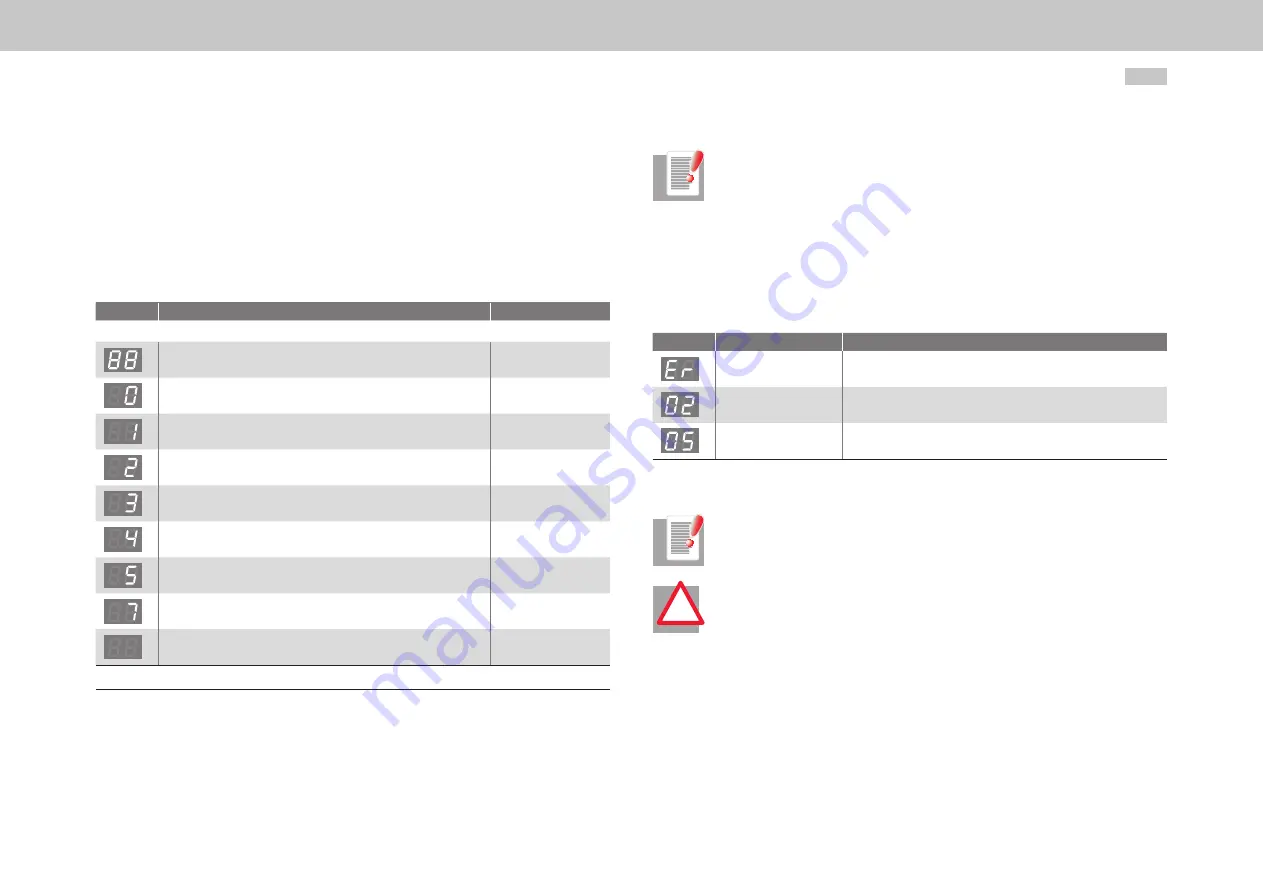
The device states can be read from the 7-segment display (D1, D2).

Display

Meaning

Parameter

System states

Device in reset state

Self-initialisation on device start up

(Start)

 1)

Not ready (no DC link voltage)

(NotReady-

ToSwitchOn)

 1)

Starting lockout (ENPO not set)(DC link precharged to ideal voltage, 

power stage not ready)

(SwitchOnDisabled)

READY (ENPO set)(power stage ready)

(ReadyToSwitchOn)

On (DC link voltage is increased to reference setpoint / soft-start 

active)

(SwitchedOn)

Power Supply Unit ready (DC link voltage setpoint reached)

(OperationEnabled)

Error reaction active

(FaultReactionActiv)

Error (for error list see section 5.2, p. 65)

(Fault)

1) Not a “Safe” display under the terms of IEC/EN 61800-5-2.

Table 5.1  Device states

NOTE:

The STO (Safe Torque Off) safety function is not required for the Power Supply 
Unit, as no motors are connected. In order to start the Power Supply Unit, a 
jumper must be placed between X4/14 and X4/22. If this jumper is forgotten, 
the fact is indicated by a flashing dot on the device display. The STO safety 
function is used in conjunction with a Multi-Axis Servo Drive.

5.1.1 

Error

In event of error alternating display: ER > 02 > 05 * ER > 02 > 05 ...

Display

Meaning

Explanation

Error

ER = Error

Error name:

02 = Error in parameter list

Description of error:

05 = Function to check current parameter list

Table 5.2  Display in case of error

NOTE:

Errors can be reset in accordance with their programmed reaction (ER) or only 
via a 24 V reset (X9/10) (ER.).

ATTENTION!

Errors marked with a dot can only be reset when the cause of the fault has 
been eliminated. 

!

Содержание G396-026

Страница 1: ...moog Power Supply Unit with sinusoidal mains feedback Programmable Multi Axis Servo Drive Power Supply Unit PSU Sizes 5 and 6A Operation Manual...

Страница 2: ...ine controller or with distributed programmable Motion Control intelligence in the servo drive the Multi Axis Servo Drive is a master of both We reserve the right to make technical changes The content...

Страница 3: ...all Mechanical installation Electrical installation Safety Specification Hardware and software Programmable Multi Axis Servo Drive Operation Manual Mechanical installation Electrical installation Safe...

Страница 4: ...ut ID YYCWxxxxx Year of production Week of production MOOG D 71034 B blingen www moog com industrial Made in Germany S N D116605 Rev A Figure 0 3 Hardware rating plate Power Supply Unit Supply package...

Страница 5: ...y y Shields and clamps Pictograms To provide clear guidance this Operation Manual uses pictograms Their meanings are set out in the following table The pictograms always have the same meanings even w...

Страница 6: ...supply connection 40 3 7 1 DC power supply connection X11 size 5 41 3 7 2 DC power supply connection X11 size 6A 42 3 8 Control connections X4 44 3 8 1 Specification of control connections 44 3 8 2 St...

Страница 7: ...6A 74 B Overview 75 Index 78 3 11 Specification of USB port X2 47 3 12 Specification of Ethernet port X3 47 3 13 Option 1 47 3 14 Braking resistor X12 RB 47 3 14 1 Connection of the external braking r...

Страница 8: ...Programmable Multi Axis Servo Drive Power Supply Unit Operation Manual ID no CA97556 001 Date 03 2015 moog 8 Table of contents...

Страница 9: ...coolant The coolant gets hot during operation Make sure the coolant has cooled down to ambient temperature before carrying out any work 1 Protection against magnetic and or electromagnetic fields dur...

Страница 10: ...2 Warning symbols used The safety instructions detail the following hazard classes The hazard class defines the risk posed by failing to comply with the safety notice Warning symbols General explanati...

Страница 11: ...and to maintain the function capability of the machine or system concerned and must be observed The function of an emergency stop system does not necessarily have to cut the power supply to the drive...

Страница 12: ...Programmable Multi Axis Servo Drive Power Supply Unit Operation Manual ID no CA97556 001 Date 03 2015 moog 12...

Страница 13: ...plate must be well earthed y y To attain the best result for effective EMC installation use a chromated or galvanised backing plate If backing plates are varnished remove the coating from the contact...

Страница 14: ...No unfiltered cables may be routed on the mains input side of the filter to prevent interference y y Servo Drives may only be installed on one side to the left or right of larger sized devices On the...

Страница 15: ...on separately from the power section so as to avoid electromagnetic interference mechanisms Control and signal cables and shields have been omitted for the sake of clarity y y Use metallically bright...

Страница 16: ...tion Manual ID no CA97556 001 Date 03 2015 moog 16 Mechanical installation 0 mm 1 2 1 Backing plate metallically bright 2 Wide area contact Figure 2 2 Servo drive installation CORRECT 0 mm 1 2 1 Varni...

Страница 17: ...ore installing the devices and components in the cabinet refer to the instructions relating to EMC installation Align Power Supply Unit size 5 and all Multi Axis Servo Drives in a line along the top e...

Страница 18: ...16 50 600 23 62 H2 15 0 59 20 0 79 H3 64 2 52 166 6 54 D 6 0 24 10 0 39 Fixing screws 4 x M5 4 x M8 E Direct butt mounted maximum 2 0 08 Direct butt mounted maximum 2 0 08 40 2 F 3 180 7 09 G 3 300 11...

Страница 19: ...e along the top edge of the unit see dotted line in Figure 2 8 This is necessary in order to execute the DC power supply using the ready made up cables Align all Multi Axis Servo Drives in a line alon...

Страница 20: ...190 7 48 280 11 02 H height 1 345 13 58 540 21 26 T depth 1 239 9 41 285 11 22 A 150 5 91 200 7 87 A1 40 1 57 65 2 56 A2 70 2 76 C 407 16 02 581 22 87 C1 6 0 24 10 0 39 H1 419 16 50 600 23 62 H2 15 0...

Страница 21: ...luid The connection set cooling circuit can be ordered separately flow return return flow 2 3 4 5 1 2 1 Liquid connection with 3 8 inch inside thread 2 90 angle connector with 3 8 inch inside and outs...

Страница 22: ...ir circulation for cooling Position the step up choke as close as possible to the Power Supply Unit Mark out the position of the tapped holes on the mounting rail Cut a tap for each fixing screw in th...

Страница 23: ...s Dimensional drawings hole spacing see Figure 2 14 and Table 2 4 Mount the input choke on the mounting rail The tapping area will provide you with good full area contact The contact area must be meta...

Страница 24: ...2 15 and Table 2 5 Mount the mains filter on the backing plate The tapping area will provide you with good full area contact The contact area must be metallically bright 2 8 1 Dimensions For size Size...

Страница 25: ...tallation must only be carried out by qualified electricians who have undergone instruction in the necessary accident prevention measures ATTENTION The device heats up in operation and at the heat sin...

Страница 26: ...ic y y Remove paint and corrosion from contact points and connect them across a wide area y y Tin plated galvanised aluminised or cadmium plated elements should be preferred to painted components This...

Страница 27: ...e subject to interference they can be made by way of coupling capacitors This enables a high frequency connection to discharge interference without transmitting the 50 Hz component y y The choke bases...

Страница 28: ...ion 1 D1 D2 T1 T2 X1 X2 X3 X4 X5 X12 SW HW Figure 3 5 Layout size 6A 3 3 Overview of connections The following shows the layout with the corresponding positions of connectors and terminals To aid orie...

Страница 29: ...nnection with shield braking resistor DC power supply connection Power Supply Unit size 6A to Multi Axis Servo Drive size 6A p 38 p 38 p 47 p 43 X21 Connection of mains synchronisation DC link prechar...

Страница 30: ...ply Unit connection diagram schematic view Key 1 Mains fuses 2 Mains supply emergency stop 3 Shield plates grey 4 Step up choke with KTY temperature sensor 5 Above a cable length of 500 mm 19 69 in sh...

Страница 31: ...ctrical installation NOTE Risk of Power Supply Unit destruction by incorrect wiring Figure 3 7 shows only a schematic view of the connection layout The positions of the terminals may vary according to...

Страница 32: ...pply Unit connection diagram schematic view Key 1 Mains fuses 2 Mains supply emergency stop 3 Shield plates grey 4 Step up choke with KTY temperature sensor 5 Above a cable length of 500 mm 19 69 in s...

Страница 33: ...conductors with a cross sectional area of 10 mm2 0 02 in2 Cu Cross sectional area of outer conductors mm2 in2 Minimum cross sectional area of corresponding PE conductor mm2 in2 Q 16 0 03 Q 16 0 03 Q...

Страница 34: ...2 p 33 Earth all other Multi Axis Servo Drives size 5 to size 1 via a common PE conductor Connect all other PE terminals X11 PE of the butt mounted Multi Axis Servo Drives in series Connect the PE te...

Страница 35: ...minals are designed as safety extra low voltage protective extra low voltage SELV PELV circuits and must only be operated with voltages from 5 V to 50 V as per the relevant specification This provides...

Страница 36: ...ENTION Take suitable measures to provide adequate cable protection e g fusing 10 A gG If the permissible current capacity is exceeded an additional separate control supply must be connected NOTE The e...

Страница 37: ...rcuit breaker see A 12 p 73 Specification of precharge and mains synchronisation X21 Precharge and mains synchro nisation L1 L2 L3 X21 HREL L3 N L1 L2 U 400 460 480 V AC IPrecharge 20 A falling over a...

Страница 38: ...DC 6 A active when precharge complete 16 Power Supply Unit size 6A 17 AC power connection 18 Braking resistor Figure 3 15 Connection of mains supply schematic view ATTENTION Danger to life Never wire...

Страница 39: ...ss section depending on the maximum current and ambient temperature Cable cross section according to local regulations and conditions Use shielded cables as shown in Figure 3 15 Wire the Power Supply...

Страница 40: ...e the ready made up cables sup plied or 35 95 mm2 0 05 0 15 in2 AWG 2 AWG 3 0 1 Tightening torque 2 5 4 5 Nm 25 30 Nm 1 Flexible cable with or without ferrule Note the following points y y Switching t...

Страница 41: ...ready made up DC power supply cables Connect terminal X11 of the Power Supply Unit to terminal X11 of the next butt mounted Multi Axis Servo Drive On the Multi Axis Servo Drive connect the DC power s...

Страница 42: ...Take off the shrink tubing on the round end Use the longer conductor for servo drives butt mounted on the right Use the shorter conductor for servo drives butt mounted on the left On the Multi Axis Se...

Страница 43: ...se The connection of the DC link must be made with parallel cables The conductor cross section must be at least 50 mm2 0 08 in2 CU The cables must be short circuit and earth fault proof and shielded T...

Страница 44: ...2 X4 7 X4 8 X4 9 Short circuit proof Imax 50 mA PLC compatible Terminal scanning cycle 1 ms High side driver Yes Table 3 6 Specification of control connections 3 8 Control connections X4 Check whether...

Страница 45: ...ISDSH ISD06 ISD05 ISD04 ISD03 ISD02 ISD01 ISD00 24V DGND RSH RSH ENPO OSD02 OSD01 OSD00 ISA1 ISA1 ISA0 ISA0 24V DGND 24 23 22 21 20 19 18 17 16 15 14 13 12 11 10 9 8 7 6 5 4 3 2 1 X4 REL X4 23 X4 24...

Страница 46: ...eded defined in P 0730 16 17 29 OUTPUT_FS_GRID_OK Mains OK frequency AND voltage within tolerance window high Table 3 8 Selectable functions of digital outputs OSD00 to OSD02 3 9 Functions of the digi...

Страница 47: ...Klixon In the event of overheating the Power Supply Unit must be disconnected from the mains supply 3 11 Specification of USB port X2 The service and diagnostic interface X2 is executed as a USB V1 1...

Страница 48: ...NTION y y The external braking resistor can only be installed in conjunction with a Power Supply Unit without an internal braking resistor y y Be sure to follow the installation instructions for the e...

Страница 49: ...5 Nm 35 4 44 2 lb in 12 20 Nm 106 2 177 lb in Table 3 10 Input choke connections WARNING The choke has no PE connection It is intended solely for installation in a cabinet as with IP00 protection the...

Страница 50: ...1 L1 L2 L3 PE PE L1 L2 L3 PE L1 1 L2 1 L3 1 PE Figure 3 25 Mains filter connections for size 5 and size 6A For size Size 5 Size 6A For model G396 026 G396 050 G396 075 G396 110 Type FFU 3 x 56 K FFU 3...

Страница 51: ...divided into the following steps DANGER FROM ELECTRICAL TENSION Never wire or disconnect electrical connections while they are live Disconnect the device from the mains supply 400 460 480 VAC before w...

Страница 52: ...4 2 1 System requirements y y Installed Power Supply Unit see section 3 p 25 Details on initial commissioning can be found in the following section 4 2 2 p 52 y y Section 2 Installation and section 3...

Страница 53: ...ialist personnel The parameter changes described in the following are used to adapt the Power Supply Unit to the parameters of the supply system and to the number and type of Multi Axis Servo Drives c...

Страница 54: ...firm Figure 4 3 Save setting 1 2 4 2 5 Setting the mains voltage and frequency of the supply system 4 The Power Supply Unit is factory configured to a 3 x 400 V AC 50 Hz system If the Power Supply Uni...

Страница 55: ...matic identification of DC link capacity and equivalent time constant of current control 5 The DC voltage controller of the Power Supply Unit regulates DC link voltage to an internally preset fixed va...

Страница 56: ...Parameter editor parameter P 0740 NOTE For the parameters to take effect even after a restart the changed settings must be permanently saved to the device and a 24 V reset performed This completes al...

Страница 57: ...3 1 Faults and warnings in Moog DriveAdministrator 5 Parameters P 0031 ErrorStack and P 0033 ActualError contain additional information on an error or warning This information is retrieved by way of t...

Страница 58: ...card y y Ethernet IP address setting display IP see section 4 4 4 p 61 Set Ethernet IP address and subnet mask y y Field bus settings display Fb see section 4 4 5 p 62 Set fieldbus address for example...

Страница 59: ...display switches back to the device state 4 4 1 Functions of buttons T1 and T2 By way of the keypad the different menus are activated and the relevant functions controlled Button Function Comments T1...

Страница 60: ...ilable y y Reset device settings to factory defaults y y Data set handling with MMC card NOTE y y It is only possible to operate the MMC if the power stage is not active y y Accessing the MMC may as l...

Страница 61: ...dress udate Byte 0 Setting of byte 0 of the IP address in hexadecimal format e g 05 for 192 168 39 5 b1 00 FF IP address udate Byte 1 Setting of byte 1 of the IP address in hexadecimal format e g 27 f...

Страница 62: ...step 7 the save operation can be aborted by pressing any button without the setting being applied Otherwise the new value is saved after five seconds y y The changed IP address is only applied once th...

Страница 63: ...C card Connect the preconfigured MMC card to the servo drive Then perform a reset of the 24 V DC control supply by pressing both buttons T1 and T2 simultaneously When the display shows the code c1 you...

Страница 64: ...or list see section 5 2 p 65 Fault 1 Not a Safe display under the terms of IEC EN 61800 5 2 Table 5 1 Device states NOTE The STO Safe Torque Off safety function is not required for the Power Supply Un...

Страница 65: ...iggering at digital input 12 Error in CAN option 00 Unknown CAN option error 01 CAN option BusOff error 02 CAN option Guarding error Table 5 3 Error list 5 2 Error list The following table lists the e...

Страница 66: ...o 02 reserved 03 reserved 04 reserved 20 PLC error Table 5 3 Error list Error number Error location Error text 03 CAN option Message transmit failed 04 CAN option Heartbeat error 05 CAN option Illegal...

Страница 67: ...ur specialists at the Moog Service Center will be happy to help y y Service Please contact us Phone 49 7031 622 0 E Mail info germany moog com Error number Error location Error text 00 User defined er...

Страница 68: ...nuous power kW 26 50 Peak power 1 kW 52 94 DC link capacitance F 900 Technical data applies to air cooled and liquid cooled housing variants 1 For 10 s 2 Approximation values Table A 1 Size 5 technica...

Страница 69: ...al data dependent on mains input voltage and controlled DC link voltage Size Size 5 Device G396 026 G396 050 X11 L L Screw size M5 Use only the ready made up cables supplied Tightening torque 2 5 4 5...

Страница 70: ...0 23 in2 AWG 0 AWG 5 0 1 Tightening torque 25 30 Nm 221 265 lb in 1 Flexible cable with without ferrule 2 With optional inserts for G396 075 to reduce the diameter 3 The PE conductor cross section dep...

Страница 71: ...with double shrink fit tube covering Flat sheath on both sides with hole 5 5 mm 0 22 in Sketch L 4 15 DC link size 6A L1 35 mm 1 38 in L2 345 mm 13 58 in 29 4 mm 0 05 in2 Round stranded copper with d...

Страница 72: ...function minimum IP54 Table A 11 Ambient conditions A 4 Hydrological data of liquid cooling ATTENTION The temperature of the cooling plate must not be more than 10 C 50 F below the ambient temperature...

Страница 73: ...d the Multi Axis Servo Drives must not be installed in areas where they are exposed to continuous shaking Climatic conditions Power Supply Unit in transit as per IEC EN 61800 2 IEC EN 60721 3 2 class...

Страница 74: ...Nm 35 4 44 2 lb in 12 20 Nm 106 2 177 lb in Table A 15 Technical data of input choke A 7 Technical data of step up choke For size Size 5 Size 6A For model G396 026 G396 050 G396 075 G396 110 Rated alt...

Страница 75: ...ns 3RV1721 1GD10 Rated current to AC 500 V 10 4 A 6 3 A No back up fuse required as short circuit proof to 100 kA Table A 19 Technical data of circuit breaker A 9 Technical data of mains filter For si...

Страница 76: ...5 p 72 4 The supplied chokes must be used 5 The devices are rated for installation in an environment of pollution severity 2 to IEC EN 60664 1 A 13 Measures to attain UL approbation UL 508C size 5 1 M...

Страница 77: ...the DC link In regenerative mode the power is stored in the DC link Temporarily surplus energy is fed back into the supply network by the Power Supply Unit in sinusoidal form 1 ON 0 OF F 0 PWR LOCK C...

Страница 78: ...ower Supply Unit and the Multi Axis Servo Drive feature special DC connections terminal X11 for electrical coupling of the DC links Each unit is supplied with ready made up DC link cables to make the...

Страница 79: ...y Unit This is not internally protected and permits higher power outputs Lower power Multi Axis Servo Drive size 5 or smaller should be connected to DC terminal X11 ZK ZK X12 L3 L2 L1 PE RB ZK ZK Powe...

Страница 80: ...ply Size 5 and size 6A 36 Cooling Liquid cooling 70 D DC power supply Size 5 X11 41 Size 6A X11 42 Size 6A X12 41 Dimensional drawings Input choke with membrane capacitor 23 Mains filter 24 Power Supp...

Страница 81: ...ponsibility 11 I IEC 364 9 IEC 60755 39 IEC EN 60079 0 10 IEC EN 60079 1 10 IEC EN 60204 10 IEC EN 60204 1 11 IEC EN 60664 1 13 51 74 IEC EN 60721 2 2 71 IEC EN 60721 3 1 71 IEC EN 60721 3 2 71 IEC EN...

Страница 82: ...Helpline 65 Shielding 27 Step up choke Connections 48 Dimensions 22 Technical data 72 T Technical data Circuit breaker 73 Input choke 72 Mains contactor 73 Mains filter 73 Mains fuse 73 Size 5 66 Siz...

Страница 83: ...Programmable Multi Axis Servo Drive Power Supply Unit Operation Manual ID no CA97556 001 Date 03 2015 moog 81...

Страница 84: ...Programmable Multi Axis Servo Drive Power Supply Unit Operation Manual ID no CA97556 001 Date 03 2015 moog 82...

Страница 85: ...land moog com France 33 1 4560 7000 info france moog com Germany 49 7031 622 0 info germany moog com Hong Kong 852 2 635 3200 info hongkong moog com India 91 80 4057 6666 info india moog com Ireland 3...

Отзывы: