56
MCP15-500.9
Hot Water Heat Coil Maintenance
If the unit is supplied with a factory installed hot water heat coil,
check the following:
1. Periodically, inspect the coils for signs of corrosion and
leaks. Repair and replacement of the coil and the
connecting piping, valves, etc., must be performed as
needed by a qualified technician.
2. For cleaning the external surface of the coil and fins
with compressed air and/or vacuum:
The coil can
remain in the unit or be removed. Use compressed air
blown into the leaving air side of the coil and/or vacuum
from the entering air side of the coil to avoid pushing
foreign material further into the coil.
3. For cleaning the external surface of the coil and fins
with a cleaning solution:
The coil must be removed from
the unit. Caution should be exercised in selecting the
cleaning solution as well as the cleaning equipment.
Improper selection can result in damage to the coil and/or
health hazards. Cleaning solutions must not be corrosive or
cause damage to copper tube/aluminum fin coils. Be sure
to carefully read and follow the cleaning fluid
manufacturer’s recommendations before using any
cleaning fluid.
4. Maintain the circulated fluid free of sediment, corrosive
products and biological contaminants. Periodic testing of
the fluid followed by any necessary corrective measures
along with maintaining adequate fluid velocities and proper
filtering of the fluid is required.
Hot Water Freeze Stat
If the unit is supplied with a factory installed hot water coil
freeze stat, check the following:
1. Disconnect the control wiring from the freeze stat terminals.
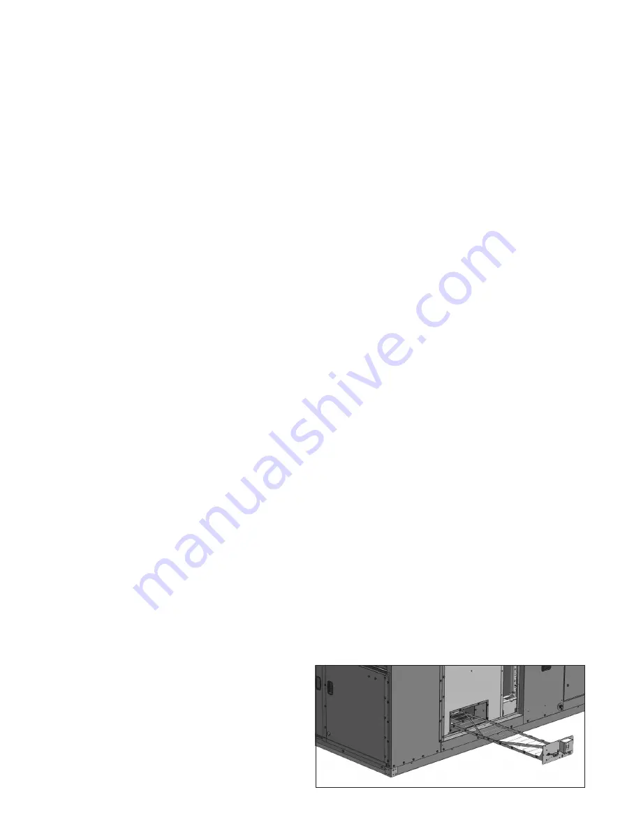
2. Remove the screws holding the freeze stat side access
panel. Refer to Figure 56.1.
3. Slide the freeze stat assembly out.
4. Examine the freeze stat capilary for cleanliness and/or
obstructions as necessary. Ensure the capillary has no
kinks or breaks (replace if either of these conditions is
present).
5. Replace the freeze stat assembly in reverse order. In
replacing the assembly, be certain that the capillary support
frame is properly located and supported. Do not force the
side access panel. It will not fit if the frame is not properly
aligned.
6. Reconnect the control wiring to the freeze stat terminals.
Figure 56.1 - Optional Factory Installed Hot Water
Coil Freeze Stat
MAINTENANCE - CONTINUED
Duct Furnace
When providing annual maintenance for the duct furnace, keep
the unit free from dust, dirt, grease and foreign matter. Pay
particular attention to:
1. The power exhauster discharge opening and the
combustion air inlet louvers.
2. The main burner orifices (avoid the use of hard, sharp
instruments capable of damaging surfaces for cleaning
these orifices). To check the main burner orifices, see
Manifold Assembly Removal section below.
3. The heat exchanger should be checked annually for cracks.
If a crack is detected, the heat exchanger should be
replaced before the unit is put back into service.
4. The gas valves and piping should be checked annually for
general cleanliness and tightness.
5. The gas controls should be checked to ensure that the unit
is operating properly.
6. If equipped with the standard efficiency (81%) gas heat
option:
a. Inspect and clean the condensate drain tray located
under the heat exchanger tube openings.
b. Inspect and clean the condensate drain tubes located on
the end of the drain tray that are routed to the outside of
the cabinet. Ensure that the tubes are not kinked or
blocked.
7. If equipped with the hybrid efficiency (D-Cabinet only) or
high efficiency (90% or 94%) gas heat option:
a. Inspect and clean the condensate drain trap and piping.
b. Fill the trap with water to ensure proper operation.
c. If a condensate neutralizer tube is installed, recharge per
the neutralizer tube manufacturer’s instructions.
d. Check the condensate overflow switch for cleanliness
and proper operation.
Manifold Assembly Removal
1. Shut off gas and electric supply.
2. Open the duct furnace control access compartment doors.
3. Disconnect gas manifold at ground union joint.
4. Remove the screws holding the manifold to the heat
exchanger support.
5. Slide the manifold through the manifold bracket.
6. Clean the orifices as necessary.
7. Slide the manifold back into the manifold bracket and
reinstall the screws that hold the manifold to the heat
exchanger support.
8. Reconnect the gas line to the manifold at the ground joint
union.
9. Turn on the electric and gas supply.
10. Check the ground union joint for leaks with a soap solution.
Tighten if necessary.
11. Close the duct furnace control access compartment doors.
Содержание MPR Series
Страница 17: ...17 MCP15 500 9 PAGE INTENTIONALLY LEFT BLANK ...
Страница 67: ...67 MCP15 500 9 PAGE INTENTIONALLY LEFT BLANK ...


