27
MCP15-500.9
START-UP PROCEDURE - CONTINUED
1
3
5
11
13
9
10
2
12
4
1
5
3
14
13
9
2
4
6
12
11
10
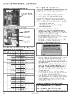
Figure 27.1 - Gas Heat Option Gas Controls - C-Cabinet Sized Units
81% Efficiency Option
(Digit
18 = J, K, L
or M)
90% Efficiency Option
(Digit
18 = U or V)
NOTE: For this option, only the left-
side furnace is shown. The right-side
furnace will be nearly identical.
1.
Power exhauster
2.
Maxitrol EXA STAR modulating gas
valve
3.
Main combination gas valve
(hidden behind Item #5)
4.
High limit control
5.
Solid state ignition control board
(cover removed)
6.
Valve state relay to Carel controller
7.
Not applicable
8.
Not Applicable
9.
Vent differential pressure proving
switch
10.
Direct spark ignitor
11.
Manifold tee pressure tap
12.
Flame sensor
13.
Manifold piping with gas orifices
14.
Condensate drain float switch
15
1
3
4
13
9
10
1.
Power exhauster
2.
Maxitrol EXA STAR modulating gas valve (right-hand furnace
only)
3.
Main combination gas valve
4.
High limit control
5.
VB1200 primary furnace control board (for right-side furnace, but
located on left side of cabinet)
6.
VB1201 secondary furnace control board (for left-side furnace)
7.
Direct spark ignition control board (cover removed)
8.
Not Applicable
9.
Vent differential pressure proving switch
10.
Direct spark ignitor
11.
Manifold tee pressure tap (primary furnace only)
12.
Flame sensor
13.
Manifold piping with gas orifices
14.
Not applicable
15.
Heat exchanger tube drain tray with drain line
Left Furnace
(Secondary)
Right Furnace
(Primary)
6
7
12
Содержание MPR Series
Страница 17: ...17 MCP15 500 9 PAGE INTENTIONALLY LEFT BLANK ...
Страница 67: ...67 MCP15 500 9 PAGE INTENTIONALLY LEFT BLANK ...


