21
MCP15-500.9
START-UP PROCEDURE - CONTINUED
Toward Motor
Set Screw
Adjustable Half
of Sheave
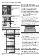
Figure 21.1 - Motor Sheave Adjustment
Blower Adjustments – Belt Drive Fans
All belt drive supply fan and, if applicable, exhaust fan speed
adjustments can be made with the adjustable sheave on the
blower motor as follows:
1. Turn off power to the unit at the disconnect switch. If
equipped with gas heat option, turn all hand gas valves to
the “OFF” position.
2. Loosen the belt tension and remove the belt.
3. On the motor sheave, loosen the set screw on the side
away from the motor (see Figure 21.1).
4. To increase the blower speed, turn the adjustable half of
the sheave inward. To decrease the blower speed, turn the
adjustable half of the sheave outward. The sheave half is
adjustable in ½ turn (180°) increments. Each ½ turn
represents approximately a 2-5% change in blower speed
and airflow volume.
5. Tighten the set screw on the flat portion of the sheave shaft.
6. Replace the belt and verify that the belts are aligned in the
sheave grooves properly and are not angled from sheave
to sheave.
7. Turn on power to the unit and initiate blower motor
operation. For guidance, refer to the latest revision of the
Controls Manual, literature #MCP74-525.
8. Check the motor amps to ensure the maximum motor amp
rating is not exceeded. Verify airflow volume and repeat
steps above for further adjustment.
9. If equipped with gas heat, turn on the gas and initiate burner
operation. For guidance, refer to the latest revision of the
Controls Manual, literature #MCP74-525.
10. Verify the temperature rise and supply air temperature of
the heating section do not fall outside the range or exceed
the maximums shown in Table 20.1. Airflow (CFM) can be
approximated with the formula from Figure 20.4.
11. After 24 hours of operation, retighten the setscrews to the
torque listed in the owners manual on the bearing, sheave,
and blower wheel to avoid damage to the unit.
Air Flow Proving Switch / Optional Dirty Filter Switch
The air flow proving switch is factory installed in the blower
compartment and acts to cut power to the controls if a positive
pressure is not measured by the switch, which would be caused
by a lack of air movement through the unit.
The optional dirty filter pressure switch is factory installed in the
filter section and monitors the pressure across the filters. When
the filters become dirty, the pressure increases and trips the
switch, initiating an alarm from the Carel controller. The switch
must be field set because setting the switch requires the blower
to be in operation and the ductwork to be installed.
Setting the Air Flow Proving or Dirty Filter Switch
1. Ensure that the unit filters are clean. Replace if necessary.
2. Using the Modine Control System controller interface, start
blower operation.
3. Turn the pressure switch set screw clockwise until it stops.
4. With the wires removed from the common and normally
open terminals of the switch, measure continuity and turn
the adjustment screw counter-clockwise until the switch
makes. Then turn the adjustment screw one additional turn
counter-clockwise to account for dirty filters or other system
static changes.
Variable Air Movement Applications
Units may be supplied with variable frequency drives for
variable air volume applications. The lowest airflow attainable is
called the Minimum Turndown Airflow (MTA) and can vary
based on the unit design airflow and nominal cooling/heating
size. The MTA can also vary between heating and cooling
modes. The following are basic guidelines for determining the
MTA capability, which can be expressed as a % by dividing the
MTA by the design airflow.
Cooling Mode
The MTA
COOLING
is the GREATER of 30% of design airflow and
the minimums shown in Table 21.1.
Example:
What is the MTA
COOLING
capability of a 10 nominal ton
B-Cabinet unit in cooling mode with a design airflow of 2000 CFM?
•
30% of 2000 CFM is 600 CFM, which is below the 800 CFM
minimum shown in Table 21.1, so 30% is not acceptable.
•
The 800 CFM minimum shown would be the MTA
COOLING
capability, which corresponds to a turndown to 40% for the unit as
configured (800 / 2000 = 40%).
Heating Mode
The MTA
HEATING
is the GREATER of 30% of design airflow and
an airflow that results in the maximum allowable temperature
rise (ATR) shown in Table 20.1 for the heat option selected.
Note that the minimum airflow is listed on the heat option serial
plate.
Example:
What is the MTA
HEATING
capability of a B-Cabinet unit in
heating mode with a design airflow of 2000 CFM and a 200,000 Btu/hr
gas heat option (Digit 18=G)?
•
30% of 2000 CFM is 600 CFM, which would result in an ATR of
250°F, which is above the 100°F maximum shown in Table 20.1,
so 30% is not acceptable.
•
The maximum ATR for the selected heat option would occur at an
airflow of 1500 CFM, which would be the MTA
HEATING
capability,
which corresponds to a turndown to 75% for the unit as configured
(1500 / 2000 = 75%).
Refer refer to the latest revision of the Controls Manual,
literature #MCP74-525 for additional information.
Cabinet Size
(Digit 6)
Nominal Tons
(Digits 4-5)
Minimum Turndown
Airflow (CFM)
j
B
7-10
800
13-20
1000
C
15-30
1550
D
30-40
1750
52-60
2450
Table 21.1 - Minimum Turndown Airflow - Cooling
j
The Minimum Turndown Airflow must not drop below 30% of design airflow.
Содержание MPR Series
Страница 17: ...17 MCP15 500 9 PAGE INTENTIONALLY LEFT BLANK ...
Страница 67: ...67 MCP15 500 9 PAGE INTENTIONALLY LEFT BLANK ...


