background image

VCU Unit Installation and Provisioning 

LTE 700 MHz MobileAccessVE Instant Coverage Solution User Manual 

19


Note:  After  the  Slave  VCUs  are  connected  (according  to  section  4.2.2),  verify  that  that  the 
Master  VCU 

VAP  Status

  LEDs,  which  correspond  to  the  connected  Slave  VCUs  complete 

initialization (blinking light) and show a solid green light. 

4.2.1.1


Master VCU Alarm Output Connections 

Note: For Master/Slave VCU configuration, the Alarms are relevant only for the Master VCU. 

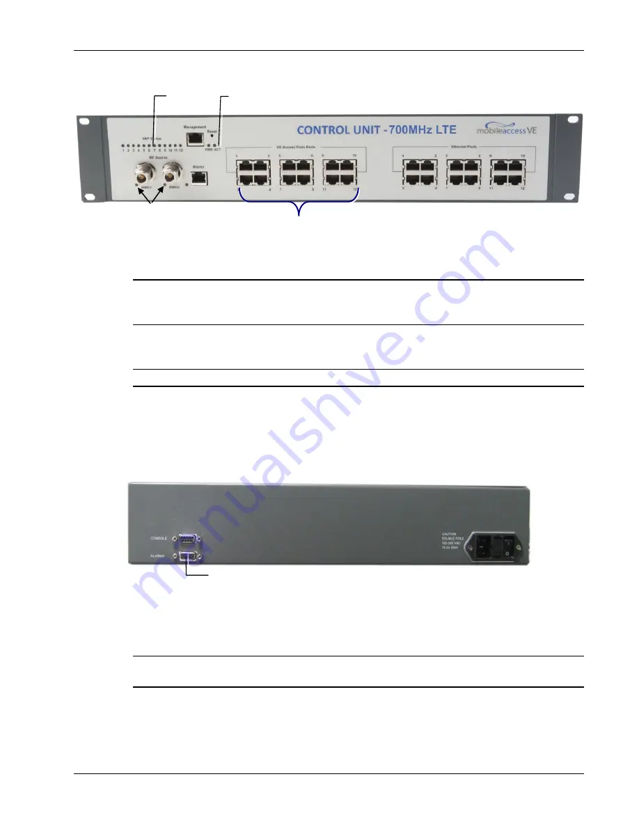
The auxiliary connections are performed through the  Master VCU rear panel 

Alarms 

port. See 

following figure. 

The  controller  can  provide  Major  and  Minor  Output  Alarms.  These  alarms  can  be  connected 
directly  to  either  the  auxiliary  input  of  the  Base  Station  or  to  any  additional  dry-contact 
application. 


A Major Alarm is generated when there is an alarm condition in one or more VCUs, while a Minor 
Alarm is generated when there is an alarm condition in one or more of the VAPs. 

Note:


If  only  one  alarm  is  required  (Minor  or  Major)  an  external  connection  of  a  wire  jumper 

between pins 8 and 13 is necessary (Normally closed). 

RF Ports 


Note: When functioning as a Master VCU and 

supporting only Slaves (no VAPs), the control 

units’ 

Ethernet Ports

 are not relevant. The 

Ethernet ports are only relevant when supporting 

mixed mode – Slave VCUs and VAPs. 

VAP Ports 1-4; 5-8; 7-12 

ACT LED 
 

VAP Status 

LEDs 

Alarms Port for Auxiliary 
Connections 


Содержание MobileAccessVE

Страница 1: ...UM_VE LTE 700 MHz MIMO_709C006202_Rev A00_08OCT10 doc MobileAccessVE LTE 700 MHz MIMO Instant Coverage Solution User Manual P N 709C006202 REV A00 Date OCT 2010 User Manual...

Страница 2: ...0 MHz MobileAccessVE Instant Coverage Solution User Manual II MobileAccess 8391 Old Courthouse Road Suite 300 Vienna VA 22182 Tel 1 866 436 9266 1 703 848 0200 TAC 1 800 787 1266 Fax 1 703 848 0280 ht...

Страница 3: ...MobileAccess uses every reasonable precaution to ensure that each unit meets their declared specifications before shipment Customers should advise their incoming inspection assembly and test personne...

Страница 4: ...OR A PARTICULAR PURPOSE MOBILEACCESS SHALL NOT BE LIABLE FOR ANY OTHER DAMAGE INCLUDING BUT NOT LIMITED TO INDIRECT SPECIAL OR CONSEQUENTIAL DAMAGES ARISING OUT OF OR IN CONNECTION WITH FURNISHING OF...

Страница 5: ...stant Coverage Solution User Manual V Certification and Compliance to Standards Category Standards Safety IEC 60950 1 2003 UL 60950 1 2003 CAN CSA C22 2 No 60950 1 03 EMC 47CFR 15 109 FCC Part 15 Radi...

Страница 6: ...information necessary for proper installation and configuration of the MobileAccessVE system List of Acronyms Abbreviation Description LTE Long Term Evolution MIMO Multiple Input Multiple Output PoE P...

Страница 7: ...mation on Location and Connections 10 3 2 Infrastructure Requirements 11 3 3 Coverage and Installation Planning 12 3 3 1 Types of Environments 12 3 3 1 1 Standard Environment 13 3 3 1 2 Open Environme...

Страница 8: ...Installations 39 5 3 1 VAP Kit Contents 39 5 3 2 Lowered Ceiling Installation 40 5 3 3 Concrete Wood Ceiling Installation 41 5 3 4 Connecting VAP and Verifying Normal Operation 43 5 4 Vertical Ceilin...

Страница 9: ...Parameters 65 9 Administrative Operations 67 9 1 Changing Password 67 9 2 Retrieving VCU IP Address 68 9 3 IP Settings 69 9 4 SNMP Configuration Parameters 71 9 5 Upgrading or Downgrading VCU and VAP...

Страница 10: ...oor and plug into existing standard Ethernet jacks They are powered via PoE technology and managed via a VE Control Unit VCU located in the floor s IDF Telco closet For site coverage that requires mor...

Страница 11: ...ered using Power over Ethernet PoE Local power is not required Minimum macro network impact with low power distributed coverage Seamlessly coexists with the Enterprise LAN and does not consume LAN cap...

Страница 12: ...rol Unit Slave VCU Installed in the IDF Telco closet and used to expand coverage to additional floors Each VCU interfaces the Master VCU and up to 12 VAPs and 12 Ethernet connections VCUs distribute w...

Страница 13: ...f the VE Control Units and Access Pods 1 3 1 VE Control Unit VCU While operating as a Master VCU Interfaces to RF source s and to VCUs VAPs Converges Wireless services and distribution to Slave VCUs S...

Страница 14: ...receives power Green Power OK Disabled No power received by VCU ACT VCU activity LED Solid Green During initialization Blinking Green Normal system operation Fast Blinking Green User activated VCU Ide...

Страница 15: ...AC 47 63 Hz AC 350W power consumption maximum 1 3 2 VE Access Pod VAP Each VAP supports Two interfaces for external antennas By default the VAP is set to transmit through the external antennas Note D...

Страница 16: ...aulty Blinking Blue Power on VAP is initializing connecting to VCU Solid Blue Power on unit operating normally Fast Blinking Blue User invoked Identify command on corresponding VAP The following figur...

Страница 17: ...Access Pods connected to the Control Units Note When locally connecting to a specific Slave VCU only the VAPs connected to this VCU can be monitored However when connected to the Master the entire de...

Страница 18: ...a local session to the Master VCU and configure the system parameters IP and service parameters Central Frequency Max expected Pin Perform a walk test and verify coverage around the floor Change VAPs...

Страница 19: ...VAPs through the cabling patch panel Wireless service signals from Master VCU to VCUs Routed through dedicated Ethernet CAT 6 7 cabling Wireless service signals from VCUs to the VAPs Routed through ex...

Страница 20: ...e 6 cabling Shielded Twisted Pair STP 24 AWG minimum diameter for CAT 5e cabling Dedicated CAT 6 7 STP cable from Master VCU to Slave VCUs with run lengths NOT exceeding 100m 300ft and no shorter than...

Страница 21: ...e LAN traffic along with the wireless service See section 4 3 If the jack is not currently active not connected to an Ethernet switch the VAP will distribute only the wireless services This section pr...

Страница 22: ...3 3 1 3 Dense Environment A dense environment consists of a relatively large amount of walls offices equipment tall file cabinets bookshelves and other items that could potentially impact the wireless...

Страница 23: ...ct RF coverage typically exterior or mirrored However this issue is not normally encountered inside a building 3 4 2 Mapping Locations To Map the VAP Locations 1 Map out the available Ethernet jack lo...

Страница 24: ...ects and would reduce coverage in that area by the other VAPs VAP 5 is an example of a unit that provides good coverage down the hallways in an Open Environment VAPs 11 and 13 are placed closer to the...

Страница 25: ...700 MHz MobileAccessVE Instant Coverage Solution User Manual 16 The following figure depicts an actual measured quantified coverage of a floor area planned according to the above rules Figure 3 3 Dist...

Страница 26: ...chapter describes the how to shift the relevant Ethernet connections required for the VAPs These steps should only be performed after planning the floor coverage and installation locations as describ...

Страница 27: ...ct or request the service provider s service personnel to connect the provider s signal source macrocell microcell BTS or BDA etc to the Master VCU front panel RF ports through passive interface Power...

Страница 28: ...an provide Major and Minor Output Alarms These alarms can be connected directly to either the auxiliary input of the Base Station or to any additional dry contact application A Major Alarm is generate...

Страница 29: ...onding to the floor being covered The Slave VCU can be installed in the rack using the supplied bracket Apply power to the Slave VCUs and note that the VCU PWR LED is lit Note that the unit ACT LED co...

Страница 30: ...jack is already in use disconnect it from the Ethernet switch and re connect it to the corresponding Ethernet port in the Slave VCU front panel 4 3 Ethernet Cable Connections to VAPs This section desc...

Страница 31: ...s Note After the Slave VCUs are installed and connected to the correct ports in the patch panels please proceed with the VAP installation as described in chapter 5 However it is recommended to complet...

Страница 32: ...for operation and remote management of the Master VCU using the Web GUI The configuration dialogs are fully described in Chapter 6 The Master or Slave mode is automatically detected according to the V...

Страница 33: ...with the default IP address 192 168 1 1 In order to communicate with the unit it is necessary to assign your computer a Static IP address in the same subnet 192 168 1 2 to 192 168 1 250 i e 192 168 1...

Страница 34: ...Master VCU IP address in the address bar Default 192 168 1 1 Note If you have forgotten the VCU IP address and or want to change it it can be retrieved via the IP Recovery Tool application provided o...

Страница 35: ...Settings tab on the side bar Note See section 6 4 for a description of the Management tab 5 Click the Modify button to define the STATIC IP Address according to existing LAN Note After the initial IP...

Страница 36: ...ter DHCP is not currently available Default definitions The Default IP Address 192 168 1 1 The Default Subnet Mask 255 255 255 0 The Default Gateway 192 168 1 254 Click OK 6 Log out and then log in ag...

Страница 37: ...U appears in the Network Topology Tree as VCU M Select the Master VCU by clicking on it 9 Before configuring the Master VCU it is recommended to give the unit an identifiable name To assign the Master...

Страница 38: ...architecture the RF parameters are only configured for the Master VCU unit Set the RF parameters according to the LTE Signal Source transmission configuration MIMO or SISO Each type of configuration...

Страница 39: ...Pin parameter can be obtained from your service provider 2 The remaining parameters are predefined to their default values Service Bandwidth is set to 10MHz per channel 3 Any updates of the service de...

Страница 40: ...arms appear 1 Verify that all the alarms are GREEN Refer to the alarm descriptions in the following table Note When SISO service is used only the Channel 1 alarms are relevant Alarm Description VCU Fa...

Страница 41: ...l 2 RF DL Pwr High alarm is masked Disabled This is the alarm for the DL signal from the BS side The left dialog shows the alarm response when Channel 2 DL RF Pwr High alarm is enabled and a fault cor...

Страница 42: ...Provisioning LTE 700 MHz MobileAccessVE Instant Coverage Solution User Manual 33 Note To briefly check the VCU status click on the VCU name in the Topology Tree The VCU icon will appear showing the LE...

Страница 43: ...ure the RF parameters individually for each connected Slave VCU It is recommended to assign each Slave VCU an identifiable name To Assign a Name to a Slave VCU 1 Connect to the Master VCU unit either...

Страница 44: ...VAP mounting installations Desk Mount Used for VAPs mounted on locations such as desks cubical walls and filing cabinets See section 5 2 2 Wall Mount Used for VAPs mounted on walls recommended high u...

Страница 45: ...nt and Wall Mount See sections 0 and 5 4 Ceiling Mount kits can be ordered separately Table 10 Desk and Wall Mount VAP Kit Kit Items Unit VE Access Pod VAPs Wall Mount Adaptor Features double sided st...

Страница 46: ...the VAP on a flat surface according to the planned location Plug the other end of the cable into the VCUs RJ 45 Ethernet jack When using an external antenna connect the Ext Antenna SMA connector s to...

Страница 47: ...aptor to the VE Access Pod using the 4 short screws Connect the VAPs RJ 45 VCU connector to the Ethernet jack leading to the VCU via RJ 45 cable supplied with VAP Plug the other end of the cable into...

Страница 48: ...d ceilings See section 5 3 3 5 3 1 VAP Kit Contents Please verify that the VAP Ceiling Mount Installation kit P N AK VAP CEILING MT H includes the items listed below Table 11 Horizontal Ceiling Mount...

Страница 49: ...e the Track Light Clip to the Ceiling Bracket top side using the provided washer and bolt 3 Hook the assembly onto the VAP rear panel grid and fit to the bottom of VAP 4 Secure the assembled brackets...

Страница 50: ...ling 7 Continue to section 5 3 4 for connections and verifying normal operation 5 3 3 Concrete Wood Ceiling Installation To Install VAP in Lowered Ceiling 1 Mark the location of the 4 screws on the ce...

Страница 51: ...top rear grid of the VAP and fit the other side on to the underside of the VAP 5 Secure the assembled brackets to the bottom of the VAP using the 4 Self Screws 6 Adjust the bracket to the VAP and tigh...

Страница 52: ...45 VCU connector to the Ethernet jack leading to the VCU via RJ 45 cable supplied with VAP Connect the Ext Antenna SMA connector s to the external antennas Note External antenna is enabled by default...

Страница 53: ...ion 5 4 2 Concrete Wood ceilings See section 5 4 3 5 4 1 VAP Kit Contents Please verify that the VAP Ceiling Mount Installation kit P N AK VAP CEILING MT V includes the items listed below Table 12 Ver...

Страница 54: ...Head Screws Note The assembly will be secured at a later stage 2 Assemble the Track Light Clip to the Large Horizontal Bracket top side using the provided washer and bolt 3 Hook the assembly onto the...

Страница 55: ...site sides of T bar Note Apply slight pressure as Twist Clip is made of spring steel Twist flanges clockwise until small flanges snap over edges The Twist Clip is now in position Place stud through 1...

Страница 56: ...rill the screws in to the marked locations on the ceiling 3 Align the three screw holes of each of the brackets Ceiling and Locke as shown in the adjacent figure and using the Flat Head Screws loosely...

Страница 57: ...tly adjust the bracket to the VAP and secure the bracket assembly 7 Hang the VAP on to the 4 screws located on the ceiling and secure the screws 8 Hang the VAP using the 4 larger screw holes on to the...

Страница 58: ...tenna connect the Ext Antenna SMA connector s to the external antenna s This option must be SW configured via the web GUI Note Internal antenna is enabled by default Note The maximum external antenna...

Страница 59: ...identifiable name corresponding to its physical location 5 7 1 Verifying Normal VAP Operation Use the RF Parameters and Module Info sub tabs to review the VAP information and status 1 If a session in...

Страница 60: ...which the VAP is connected In case you replace the VAP the newly installed VAP will automatically be set with same alarm mask 2 For more information on the VAP Alarms refer to section 8 2 5 7 2 Naming...

Страница 61: ...e initial configuration as explained in 4 4 1 the MobileAccessVE system can be accessed via the network To Access the System 1 Open a web browser In the address bar type the Master VCU s IP address as...

Страница 62: ...displayed by default Note The Monitor Events Setup and Help tab are future options The appearance of the each screen varies according to the tab displayed The Main Menu Bar tabs are Config uration Di...

Страница 63: ...e Select the Configuration tab from the menu bar The information and parameters displayed in the Configuration sub tabs vary depending on whether a VCU or VAP is selected in the topology tree The Conf...

Страница 64: ...ppear in the topology as grayed out in case they get disconnected The network elements are displayed in two levels First Level Up to 12 VCUs Second Level Up to 12 VAPs connected to each VCU Note The r...

Страница 65: ...nection is no longer detected it will not disappear from the topology but will appear in gray In order to remove a unit from the baseline so that it no longer appears in the network topology it must b...

Страница 66: ...ssVE Instant Coverage Solution User Manual 57 6 3 2 Configuration Display Area When selecting an element Master VCU Slave VCU or VAP in the network topology tree an icon representing the unit is displ...

Страница 67: ...menu tabs Firmware Used for upgrading downgrading SW to VCUs Distribute Used for distributing the upgrade downgrade SW files to the VAPs Security Used for changing user passwords SNMP Config Used for...

Страница 68: ...nfig Module Info sub tab The tab includes two additional options Identify Button Enabling this option enables finding the physical location of the selected element See section 10 1 When this option is...

Страница 69: ...ected element See section 10 1 When this option is set to ON the LEDs on the corresponding VAP VCU flickers Reset Button SW reset of the unit 7 2 Viewing VCU Alarms The alarms displayed in the Alarms...

Страница 70: ...n 3 dB Note Channel 2 alarm is not displayed when SISO service is used Service Off User has disabled the service Overall Status Indicates Fault RED level if there are unmasked faults or GREEN if there...

Страница 71: ...lected option determines the displayed RF parameters DL CF Set read only center frequency from BTS according to LTE 700 MHz range Band 13 upper Block The CF is the same for both UL and DL signals UL S...

Страница 72: ...on of the selected element When this option is set to ON the LEDs on the corresponding VAP flickers Reset Button SW reset of the unit To View VAP General Information Click the Config tab in the main m...

Страница 73: ...Button SW reset of the unit Note VAP Name is saved in the VCU associated to the port to which the VAP is connected If you replace a VAP the new one will be associated with the same name If you do not...

Страница 74: ...able length limitation In such cases the system continues to provide the wireless services but you should check the coverage of the VAP as output power may be degraded due to excess cable loss and che...

Страница 75: ...red normal level Low output power will be attenuated by 5 dB less than the required level This option can be used for smaller coverage areas that do not require the full power of the VAP for coverage...

Страница 76: ...software management procedures 9 1 Changing Password The Management Security tab provides password change options To Set the Application Password or Change an Existing Password 1 Select the Security...

Страница 77: ...h the VCU is to be connected 2 Double click on the Recovery Tool Setup and follow the prompts Standard installation procedure To Retrieve the VCU IP Address 1 Connect the computer on which the Recover...

Страница 78: ...5 To modify the current IP Parameters click Change The Change IP Parameters dialog appears Enter the new parameter value and click OK and Exit 9 3 IP Settings The IP Settings tab is used for viewing...

Страница 79: ...Administrative Operations LTE 700 MHz MobileAccessVE Instant Coverage Solution User Manual 70 Click Modify button to change settings...

Страница 80: ...P communities in which the devices and management station belongs and to where the traps are sent The SNMP default communities are Read public Write private The Community Names can be modified by clic...

Страница 81: ...s of files are stored on the VCU and on individual VAPs Active software on which the unit operates and Standby software The Active and Standby software can be swapped on each individual unit In additi...

Страница 82: ...left side In the Load New Firmware display area click the Browse button Browse for the file to be loaded from your computer location The Download button appears and the progress bar will show the dow...

Страница 83: ...stored as the Inactive version in the VAPs Set the new software as the Active version in the selected VAPs by clicking the Swap button The VAP upgrade procedure is complete Notes 1 As during the dist...

Страница 84: ...a click the Browse button Select the file to be loaded from your computer location The Download button appears and the progress bar will show the download status After the download is complete the dow...

Страница 85: ...to its physical location as explained in section 5 6 If a name was not configured or for some other reason a specific VAP cannot be physically located identify the VAP according to the instructions in...

Страница 86: ...ponding Access Pod will start blinking fast You will need to physically locate the VAP to see the blinking LED 4 Locate the Access Pod 5 It is advisable to assign it an identifiable name via the Acces...

Страница 87: ...3 Verify correct settings of center frequency and system gain See DL CF and UL System Gain parameters in RF Parameters sub tab see example displayed above 4 Verify that the RF cables are properly conn...

Страница 88: ...ice from Connected Access Pod This requires physically accessing the Access Pod to check the LEDs and accessing the Access Pod through the Web GUI to verify the Access Pod configuration 1 Physically v...

Страница 89: ...80 Select the VAP from the topology tree and click the RF Parameters sub tab Confirm that the VCU port is functioning VAP Status LED top LED in VAP icon associated with this Pod is green Note The Acti...

Страница 90: ...y that the VCU is powered ON 2 Verify that the SNMP traps destination address is configured correctly 3 Verify the IP connectivity to the Fault Monitoring server using ping 4 Verify that SNMP port is...

Страница 91: ...rviceOff Service is off 4 vcuChannel_2_DLPowerLow Input RF power is Low or no signal 5 vcuChannel_2_DLPowerHigh Input RF power is above the max expected Pin 6 vcuChannel_2_ServiceOff Service is off 7...

Отзывы: