MODEL 250DP DUAL PULSE
RESISTANCE WELDING POWER SUPPLY
990-280
vii
ILLUSTRATIONS
Figure Title
Page
1-1
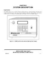
250DP Dual Pulse Resistance Welding Power Supply ............................................................... 1-1
2-1
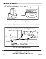
Cable Routing Examples
.......................................................................................... 2-2
2-2
Terminal Connection Examples
.......................................................................................... 2-2
2-3 Rear
Panel
Components
.......................................................................................... 2-3
2-4
Typical Solenoid Air Valve Assembly with a Single egulator ................................................... 2-6
2-5
250DP Equipment Interconnection Diagram .............................................................................. 2-9
3-1 Front
Panel
Controls
.......................................................................................... 3-1
3-2
Screen Flow Chart
.......................................................................................... 3-5
4-1
Typical Solenoid Air Valve System with Dual Regulators ........................................................ 4-2
4-2
Typical Solenoid Air Valve System with a Single Regulator ..................................................... 4-3
4-3
Measuring Preset Firing Force of the Weld Head with a Force Gauge ...................................... 4-4
4-4
Results of Excessive Air Pressure
.......................................................................................... 4-5
4-5
Weld Head Configuration Jumper Selection .............................................................................. 4-6
5-1
Effects of Excessive or Insufficient Heat, Time and Pressure .................................................... 5-2
5-2
Typical Weld Strength Profile
.......................................................................................... 5-7
7-1
Line Voltage and Capacitor Bank Jumpering ............................................................................. 7-2
7-2
100 VAC Line Voltage Configuration ........................................................................................ 7-4
7-3
115 VAC Line Voltage Configuration ........................................................................................ 7-5
7-4
208 VAC Line Voltage Configuration ........................................................................................ 7-6
7-5
230 VAC Line Voltage Configuration ........................................................................................ 7-7
A-1
Rep/Hit Rate with 1500 μF Capacitor Bank .............................................................................. A-5
A-2
Rep/Hit Rate with 3000 μF Capacitor Bank .............................................................................. A-5
A-3
Pin Numbers as Viewed from the Rear Panel .......................................................................... A-11
A-4
Jumper Selection for Air Valve Driver Control ....................................................................... A-15
A-5
CONTROL SIGNALS Connector
....................................................................................... A-16
A-6
Remote Schedule Selection with a Remote Binary Switch ..................................................... A-18
A-7 250DP
Dimensions
....................................................................................... A-22


