CHAPTER 4: GETTING STARTED
MODEL 250DP DUAL PULSE
RESISTANCE WELDING POWER SUPPLY
990-280
4-3
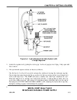
5 Unlock the regulator(s) by pulling the red ring up. Set the air gauge(s) for 25 psig. Fully open both
flow controls.
6 The operational sequence with an air head is as follows:
The first level of a 2-Level foot switch actuates the weld head, moving the electrodes together.
The weld period cannot begin until the second level of the foot switch
and
the force firing switch
in the weld head close. The 250DP will enter a standby state until these conditions are met.
When the firing force is reached, the weld period will start. Assuming that an alarm does not
occur, the welding sequence will continue to completion and the weld head will rise at the end of
the hold period. If FOOT SWITCH WELD ABORT is ON, releasing the foot switch at any time
during the welding sequence will terminate the sequence.
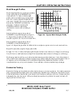
Figure 4-2. Typical Solenoid Air Valve System with
a Single Regulator


